Page 7 of 16
The Matrix network is designed to conveniently accommodate a large number of accessory devices. As more products utilizing CAT5
connectivity are integrated into the vehicle, routing of the cables can be accomplished in ‘daisy chain’ fashion, if desired. Serial lightbars
utilizing CAT5 will always be the last device in either the PRI-1 or SEC-2 chain. Further instructions, features, and control options are
detailed in the installation manual of the customer selected central node.
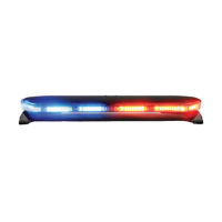
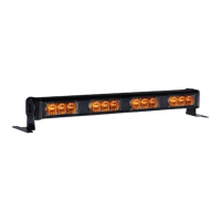
The following table indicates the default ash patterns of the serial lightbar. These patterns are activated by other Matrix compatible
products, connected to the lightbar. These can easily be recongured as desired, in the Matrix Congurator. See Matrix Conguration Quick
Start Manual for details.
Flash Patterns
Default Description
Arrowstik Right Building Fast
Right Scene Steady
Left Scene Steady
Takedown/Alley Flash Single Flash 150 - Alternating
Arrowstik Left Building Fast
Dim 30%
Cruise Dim, Full Bar
Level 3 Pursuit - Alternating
Level 2 Triple Flash 115
Level 1 Sweep
Takedown Steady
Front Cut
Arrowstik Flash Quad Flash 115