Page 6 of 16
Wiring Instructions:
IMPORTANT! This unit is a safety device and it must be connected to its own separate, fused power point to assure its continued operation
should any other electrical accessory fail. Do not wire in parallel with any other accessory.
Notes:
• Larger wires and tight connections will provide longer service life for components. For high current wires it is highly recommended
that terminal blocks or soldered connections be used with shrink tubing to protect the connections. Do not use insulation displace-
ment connectors (e.g., 3M Scotchlock type connectors).
• Route wiring using grommets and sealant when passing through compartment walls. Minimize the number of splices to reduce volt-
age drop. High ambient temperatures (e.g., under-hood) will signicantly reduce the current carrying capacity of wires, fuses, and
circuit breakers. All wiring should conform to the minimum wire size and other recommendations of the manufacturer and be pro-
tected from moving parts and hot surfaces. Looms, grommets, cable ties, and similar installation hardware should be used to anchor
and protect all wiring.
• Fuses or circuit breakers should be located as close to the power takeo points as possible and properly sized to protect the wiring
and devices.
• Particular attention should be paid to the location and method of making electrical connections and splices to protect these points
from corrosion and loss of conductivity.
• Ground termination should only be made to substantial chassis components, preferably directly to the vehicle battery.
• Circuit breakers are very sensitive to high temperatures and will “false trip” when mounted in hot environments or operated close to
their capacity.
Caution:
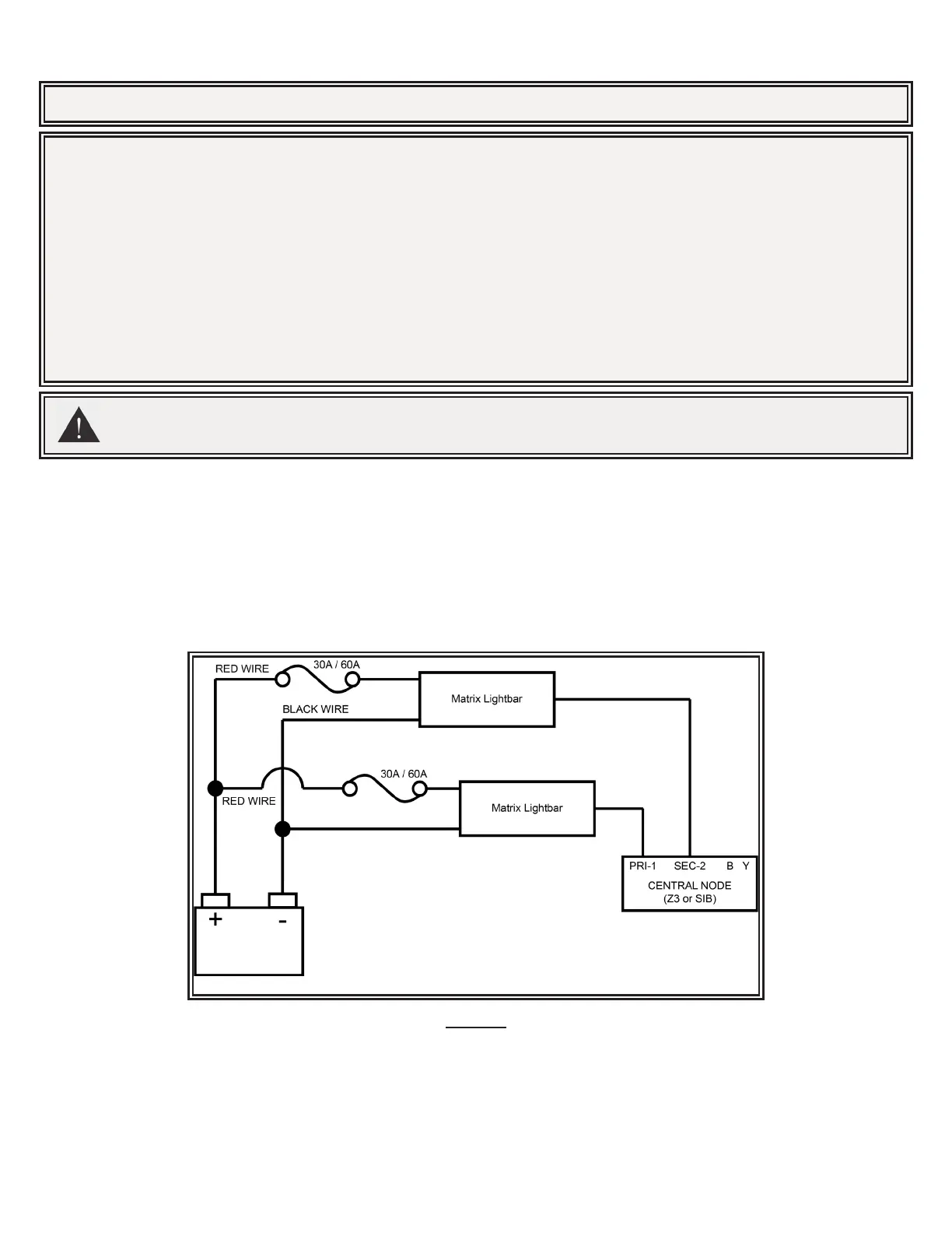
Disconnect the battery before wiring up the lightbar, to prevent accidental shorting, arcing and/or electrical shock.
Connect the red (power) and black (ground) wires from the serial lightbar to a nominal 12 VDC supply, along with a customer supplied in-line,
slow blow ATC style fuse. Check the box label or wire tag to determine if your lightbar requires a 30A or 60A fuse. This depends on the
number and type of light modules installed inside. Nothing less than a 30A fuse is permitted. Please note that the fuse holder selected by
the customer must also be rated by its manufacturer to meet or exceed the corresponding fuse ampacity. See Figure 5 for details.
All Matrix compatible lightbars should also connect back to a central node, such as the Serial Interface Box or Z3 Serial Siren, to establish
serial communication with the larger network. Depending on the lightbar model, this cable will involve either a CAT5 connection or bare wire,
twisted pair termination labeled B Y at the central node. Connect the serial lightbar to your central node, according to the Matrix connectivity
specied for the particular model at the beginning of this document. Please note, for CAT5 connections the PRI-1 port must always be
utilized rst, before additional devices can be connected to the SEC-2 port. See Figure 5 for details.
Figure 5
 Loading...