4 caSEC revB
DBI PORT
CASEC
# 4360713
FLCART PROGRAMMING PORT
FLCART PORT
FLCART HARNESS PORT
WHITE/RED PARKING LIGHT INPUT
WHITE PARKING LIGHT OUTPUT
BLACK GROUND
BROWN SIREN OUTPUT ( + )
RED BATTERY 12V ( + )
SHOCK SENSOR PORT
BLUE/WHITE INSTANT TRIGGER INPUT ( - )
GREEN DOOR TRIGGER INPUT ( - )
ORANGE GROUND WHEN ARMED ( - )
PURPLE DOOR TRIGGER INPUT ( + )
YELLOW IGNITION INPUT ( + )
RED/WHITE TRUNK RELEASE OUTPUT ( - )
BROWN/BLACK HORN OUTPUT ( - )
VIOLET/BLACK AUX 1 ( - )
LT GREEN/BLACK FACTORY DISARM OUTPUT ( - )
BLUE UNLOCK OUTPUT ( - )
OPEN
GREEN LOCK OUTPUT ( - )
PINK/BLACK AUX 5 OUTPUT ( - )
ORANGE/BLACK AUX 4 OUTPUT ( - )
GRAY/BLACK AUX 3 OUTPUT ( - )
WHITE/BLACK AUX 2 OUTPUT ( - )
#1032368
#1031421
#4120184
#1031423
RED
BATTERY 12V ( + )
BLACK
GROUND WHEN ARMED ( - )
BLUE FULL TRIGGER ( - )
GREEN WARN AWAY TRIGGER ( - )
SHOCK SENSOR & HARNESS
#4700023
ORANGE 86 - ARMED OUTPUT ( - )
RED 85 - IGNITION ( + )
BLACK 87A - STARTER OUTPUT - MOTOR SIDE
WHITE / BLACK 30 - STARTER INPUT - KEY SIDE
STARTER INTERUPT RELAY & HARNESS
86
85
87
87a
#1024405
Programming Note:
P
The default wire function settings are listed next
to the wire color. Wires shown with can be
programmed to perform different functions.
Refer to the Feature Programming section to
change the default setting.
P
P
P
P
P
P
P
P
P
P
P
P
Replacement Part
(4-Pin)
Replacement Part
Input / Output
Harness
(9-Pin)
Aux Output
Harness
(4-Pin)
Replacement Part
ANTENNA
LED
VALET
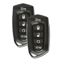
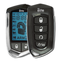
** RF KITS SOLD SEPERATELY **
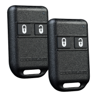
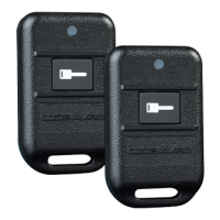
Replacement Parts
1-Way # 4180065
2-Way # 4180064
Harness (4-Pin)
# 4120388
ANTENNA PORT
Replacement Part
Door Lock Harness
(3-Pin)
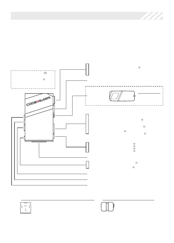
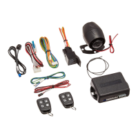
Wire Connection Guide
System Layout
This diagram shows the available harnesses and connections for the caSEC. Note that
you may not use all connections and modules in your installation.