Code Blue
•
259 Hedcor Street
•
Holland, MI 49423 USA
•
800.205.7186
•
www.codeblue.com
GU-157-AApage 34 of 76
CB 1 Series
Administrator Guide
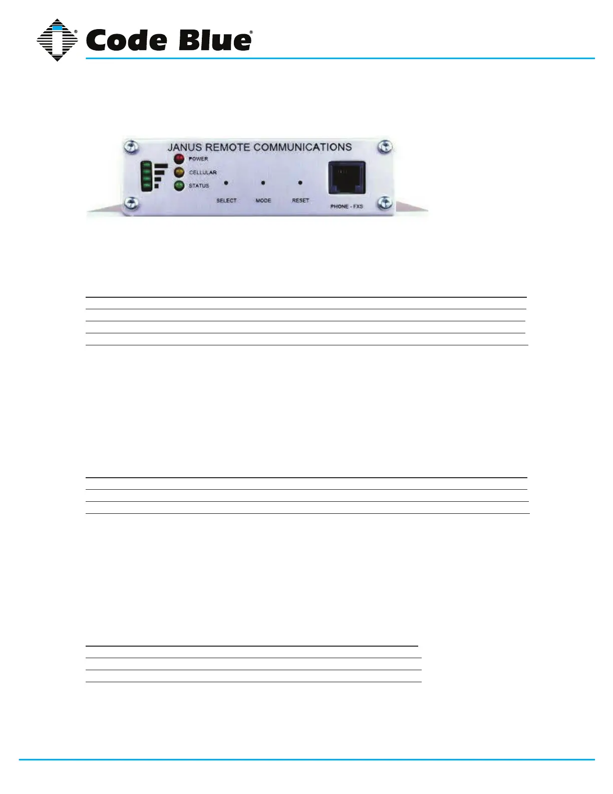
GSM-5 LED Indicator Readout
External Interfaces - Front Panel
Received Signal Strength Indicator
A stack of 4 green LED’s on the left side of the front panel indicate the relative signal strength of the
cellular radio signal. It is analogous to the ‘bars’ display on a cellular telephone handset.
RSSI Indicator
LED’s ILLUMINATED SIGNAL STRENGTH RSSI (dBm)
4 Excellent -73 or better
3 Good -83 to -74
2 OK -93 to -84
1 Marginal -109 to -94
If no signal is detected, the LED’s on the stack alternately illuminate from bottom to top and back in a
‘scanning’ manner.
GPS Indicator
The bottom (#1 ‘Marginal’) LED on the RSSI indicator will blink several times for 1 second every 10
seconds to indicate a GPS location x is available. This indication is independent of the cellular signal
strength indication.
LED Operational Indicator
LED LED COLOR INDICATION
POWER Red Power status
CELLULAR Yellow Cellular radio status
STATUS Green System status
General status conditions can be inferred as follows:
• Green and Yellow LED continuously ON: during initialization (following the application of power
or a manual RESET).
• Yellow LED blinks every 2.5s – wireless registered on network.
• Yellow LED ON - when cellular call connected.
• Green LED fast blink - when on hook (no call in progress)
• Green LED - ON when off hook (during call)
Power (red) LED
LED STATUS INDICATION
ON System is powered
OFF System has no power
Blinking System Fault