Code Blue
•
259 Hedcor Street
•
Holland, MI 49423 USA
•
800.205.7186
•
www.codeblue.com
GU-157-AApage 33 of 76
CB 1 Series
Administrator Guide
GSM-5
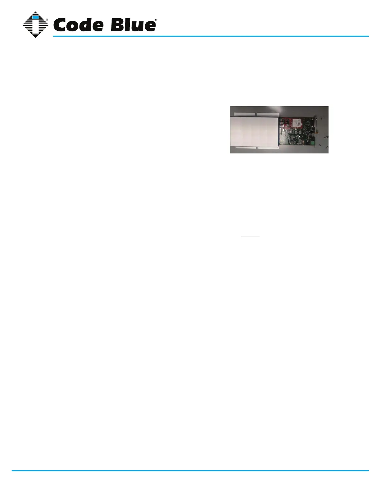
Installing the GSM-5
1. Before mounting the GSM-5 box, open the box by removing the four screws on the Power
Input side of the GSM-5, you can slide out the tray and insert the SIM Card into the SIM Card
holder. Unlock the card holder and tilt it up. Now insert the SIM card with the contacts facing
the PCB. Set the SIM card hold down at parallel with
the board and slide to lock position. Next return tray
back in and secure screw in place.
2. Place the new GSM-5 in the same location, using same
hanging method as the Telular Box did.
3. The new antenna (pulled in when you removed the
original antenna), can now be threaded on to the GSM-5
SMA bulkhead tting on the side of the blue box.
4. GSM-5 Power connection: ID the positive and negative terminal from the previous device
and mate the wire connections
5. GSM-5 modular phone cable will directly plug into the CB2000 or IA4100 series phones di-
rectly. If you have the IA3100 speaker phone, it has a screw terminal connector in place of a
Phone jack. Suggest you reuse the IA3100 phone cable in place of the GSM-5 phone cable.
The RJ-11 connector will t through the water tight tting without damaging the RJ end.
6. Review all electrical connections related to the GSM-5: Antenna, Phone line, Power (along
with its correct polarity). CONNECT BATTERY POWER, BACK UP, THEN MAIN POWER in
the case of NightCharge™
7. Watch the status lights on the GSM-5 for registration, is the middle LED indicator constant =
Registered. See GSM-5 LED Indicator Readout below
8. Place the speakerphone back into the enclosure, and replace the screws.
9. Activate the phone to test the GSM-5 ability to place a call. If you’re able to place a complete
a call, it’s time to wrap it up. If not call Tech Support for assistance.
10. Replace the service door and screws