Code Blue
•
259 Hedcor Street
•
Holland, MI 49423 USA
•
800.205.7186
•
www.codeblue.com
GU-157-AApage 60 of 76
CB 1 Series
Administrator Guide
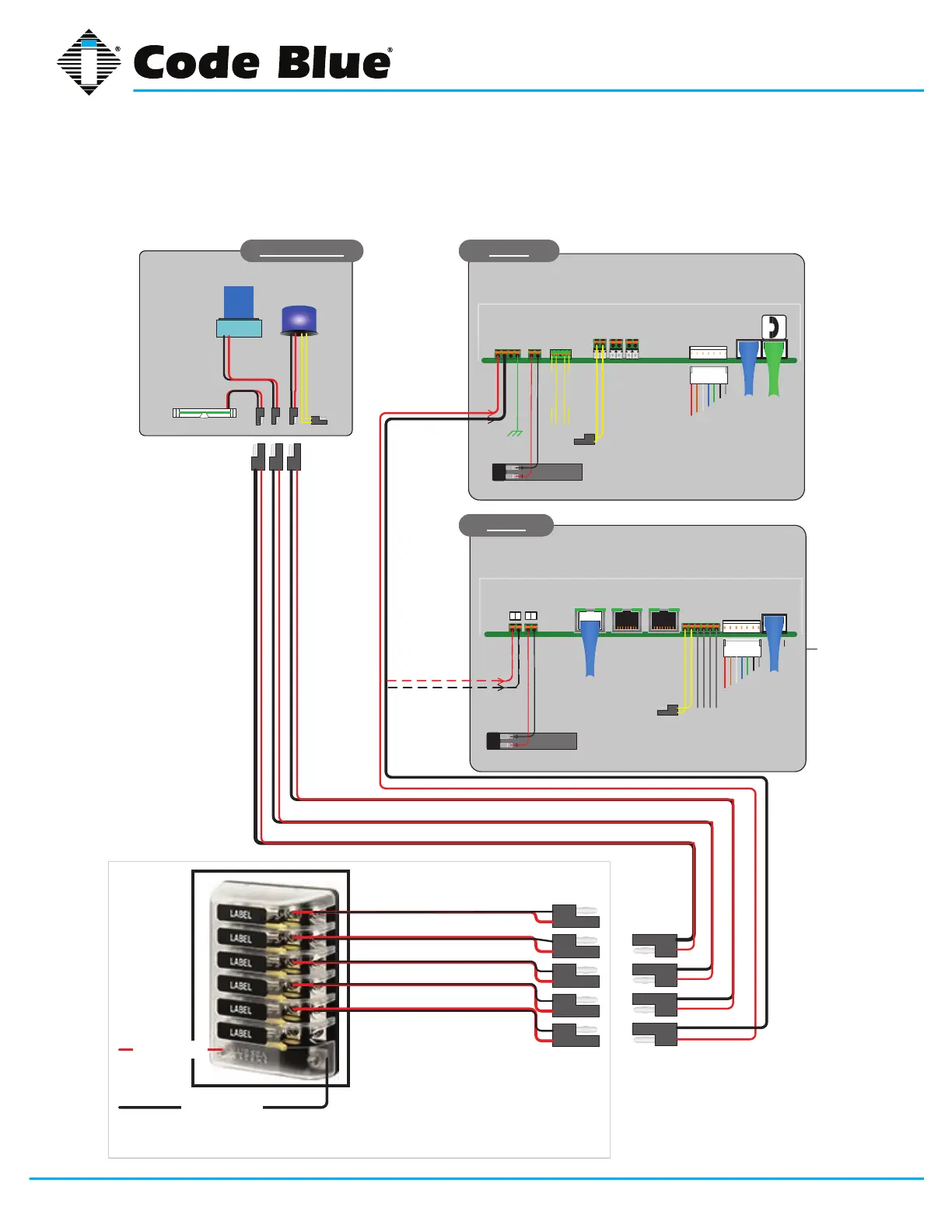
33 CB 1-e 24V Standard Wiring (after 2015)
(with Fuse Block)
Product wiring diagram shown reasonably represents current offering and is intended to assist in component identication and service. Earlier product
production may have different components and wiring connections. Reference the model and serial number from the unit ID tag and contact
manufacturer to conrm replacement part version and availability.
LV Positive
LV Negative
Beacon Strobe
12 – 24 Volts AC or DC
LED Area Light
24 Volts AC / DC or
12VDC
CB1 s&d
CB2s units only
Lighting Units
Strobe
Trigger
LED Faceplate light
12 – 24 Volts AC or DC
LANLAN
LAN
PoE
PAS
Control
Aux ports
PAS
Audio
+
-
+
-
IP5000
Audio Output
1
Optional Battery 12V @ 2.0Ahr
12 – 24 Volts AC or DC
Ethernet
Aux Output 2
Aux input 1
Aux Output 1
1
Inputs
Aux input
1
Aux input
2
Phone line
Audio Output
+
-
G
+
-
Output
1 2 3
N.O.
N.C.
PAS
Control
PAS
Audio
IA4100
Battery 12V @ 2.0Ahr
12 – 24 Volts AC or DC