9
D027166_02 User Manual
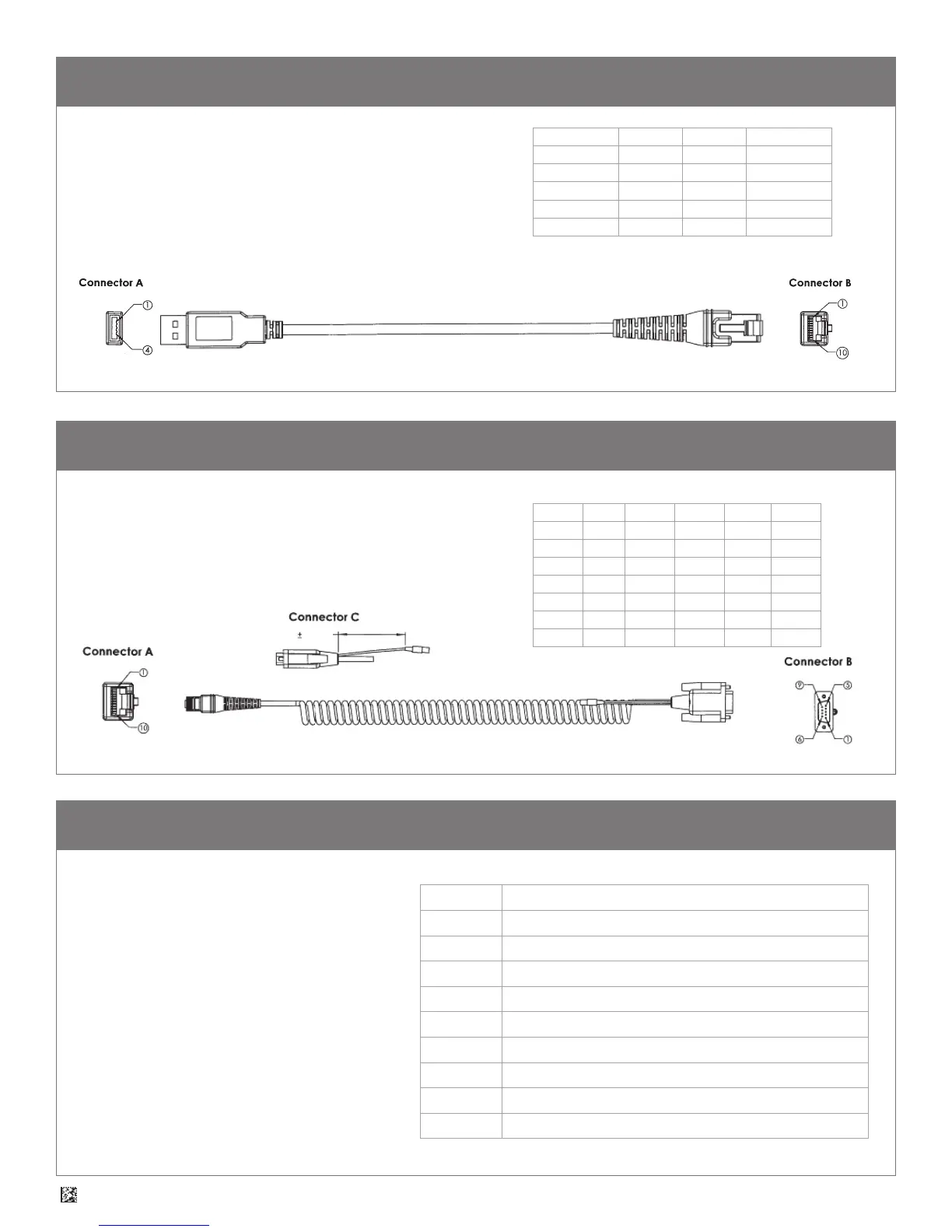
13.0 - USB Cable Example with Pinouts
14.0 - RS232 Cable Example with Pinouts
NOTES:
1. Part to be ROHS and Reach compliant.
2. Maximum Voltage Tolerance = 5V +/- 10%.
3. Caution: Exceeding the maximum voltage will void
manufacturer warranty.
CONNECTOR A
CONNECTOR B
NOTES:
1. Part to be ROHS and Reach compliant.
2. Maximum Voltage Tolerance = 5V +/- 10%.
3. Caution: Exceeding the maximum voltage will void
manufacturer warranty.
CONNECTOR A NAME WIRE CONNECTOR B
1 VIN 26 AWG 1
2 DM 24 AWG 2
3 DP 24 AWG 3
4 GND 26 AWG 10
SHELL - SHIELD NC
CONN A NAME WIRE CONN B WIRE CONN C
1 VIN 24 AWG 9 24 AWG TIP
4 TX 26 AWG 2
5 RTS 26 AWG 8
6 RX 26 AWG 3
7 CTS 26 AWG 7
10 GND 24 AWG 5 24 AWG RING
NC - SHIELD SHELL
15.0 - Reader Pinouts
The connector on the CR950 is an RJ-50
(10P-10C). The pinouts are as follows:
Pin 1 +VIN (5v)
Pin 2 USB_DM
Pin 3 USB_DP
Pin 4 RS232 TX (output from reader)
Pin 5 RS232 RTS (output from reader)
Pin 6 RS232 RX (input to reader)
Pin 7 RS232 CTS (input to reader)
Pin 8 External Trigger (active low input to reader)
Pin 9 N/C
Pin 10 Ground
6 IN 0.5 IN