ELECTRICAL AND ELECTRONIC SYSTEM
Functional Description
23. The MPU Controller Board employs Microprocessor technology to monitor and control the
operation of the beverage machine. The board contains the main System Program, the
Operator’s Program and the Engineer’s Program, each stored in programmable read only
memory.
24. Variables, such as the amount of ingredients dispensed, are stored in non-volatile random
access memory (NVRAM) and are called up by addressing either the Operator’s Program
or the Engineer’s Program as appropriate.
25. The main System Program tasks the microprocessor with continually checking the status of
the input devices (keypad, probe, etc.) and responding to data received by signalling the
output devices (LCD display, motors, whippers etc.) to take the appropriate action. The
System Program also requests the microprocessor to interrogate the variable settings in
NVRAM and to modify its actions accordingly.
26. Output transistors and F.E.T. devices on the MPU Controller Board convert signals from the
Controller’s microprocessor circuit to the current drive necessary to operate output devices,
i.e. motors, whippers and inlet valve.
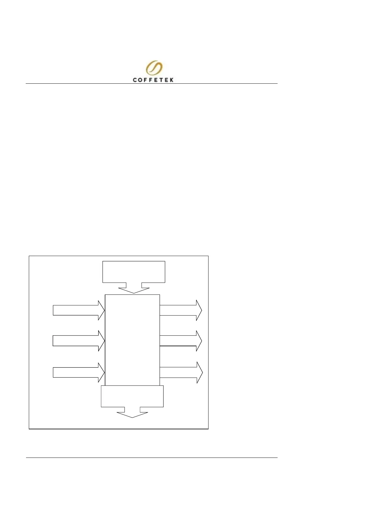
FIG 1.3 ELECTRICAL &
ELECTRONIC SYSTEM
– FUNCTIONAL
DIAGRAM
HEATER SSR'S
VALVES
MOTORS/FAN
CONTROLLER
BOARD
WATER LEVEL
KEYPAD
TEMP SENSOR
Capacitive Touch
Screen Selection
 Loading...