11
AETERNA CHANGE-GIVER COIN MECHANISM REL. 2.7
®
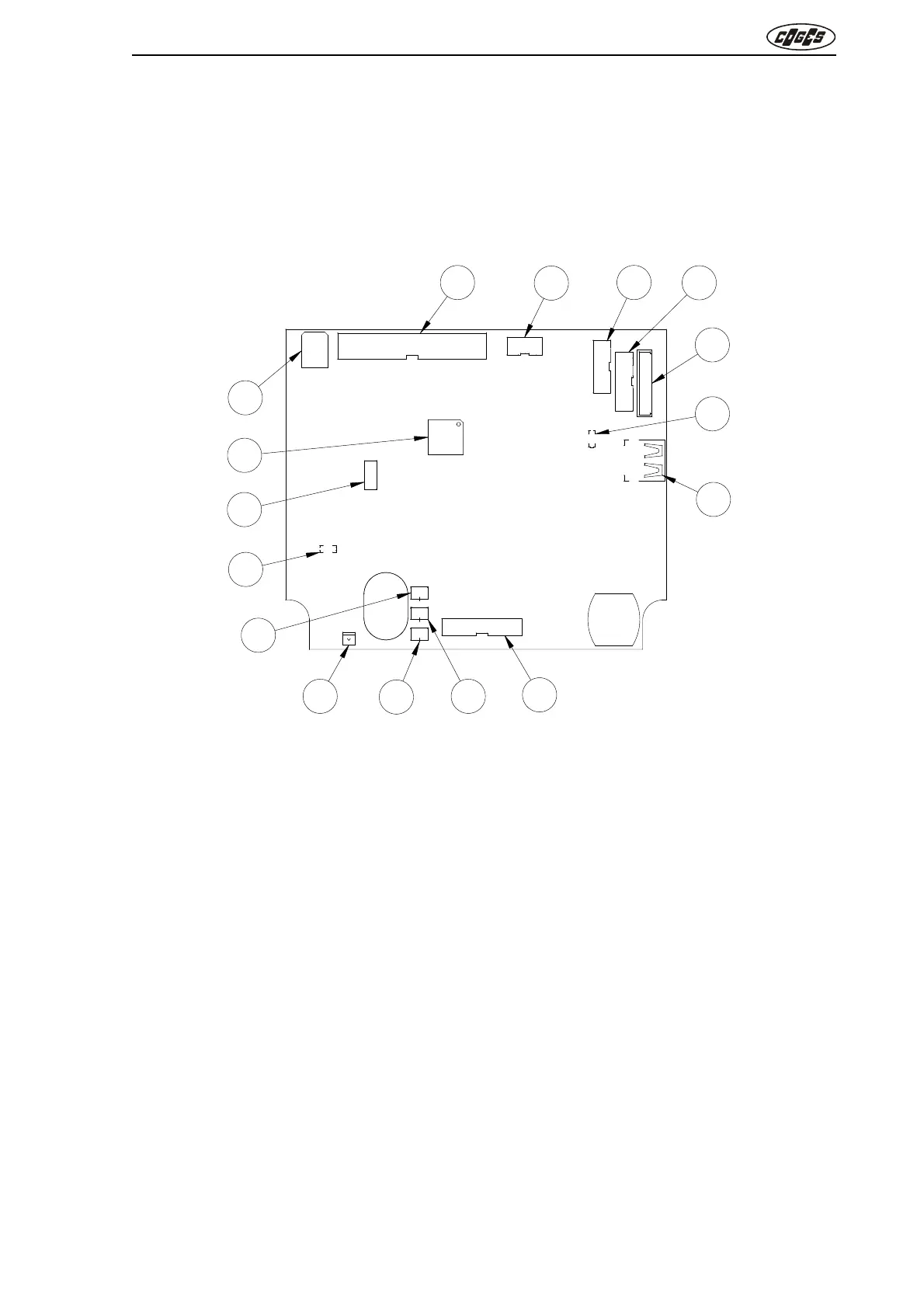
1.3.4. Base board
In the Base Board there is the main firmware of the Change-giver Coin Mechanism with all the con-
trol functions on the sales and the credit management, the reference model for the coins and the
management of all the mechanical and electronical functions of the Coin Mechanism.
The firmware update of the Base Board and the model are described in detail at the end of chap-
ter 3 (see para. 3.4. “Firmware update”).
fig. 5
1 = Flat 34-ways connector for Coin Validator (J12)
2 = Minitek 2x5 ways connector for IR PORT Module, PC programming interface for systems/
validators, harness for serial communication to PC and Comunica Module (J4)
3 = Minitek 2x8 ways connector for vending machine (J9)
4 = Minitek 2x9 ways connector for MDB peripherals (J7)
5 = Modu2 8-ways connector for electromechanic interface (J13)
6 = Yellow LED for flash programming (DL1)
7 = Connector for internal use (J5)
8 = Flat 20-ways connector for photocells, coin distribution motors and box presence (J10)
9 = Molex 2-ways connector for coin distribution motor for tube 2(J2)
10 = Molex 2-ways connector for coin distribution motor for tube 3-4 (J3)
11 = White LED for tube lighting (DL3)
12 = Molex 2-ways connector for coin distribution motor for tubes 1-5 (J1)
13 = Green LED for power supply (DL2)
14 = Connector for internal use (J6)
15 = Microprocessor (U8)
16 = Connector for printer (J14)
34
33
2
J12
1
2
1
J7
2
1
J9
J10
20
19
2
1
1
J1
1
1
J3
J14
J4
DL3
81
J13
J5
J2
1
J6
1
2
3
4
5
6
7
8
9
10
11
12
13
14
15
16
DL1
DL2