InteliCharger 240 24 Reference Guide
10
See chapter Battery output wiring diagram (page 7) for details.
Signal output terminals
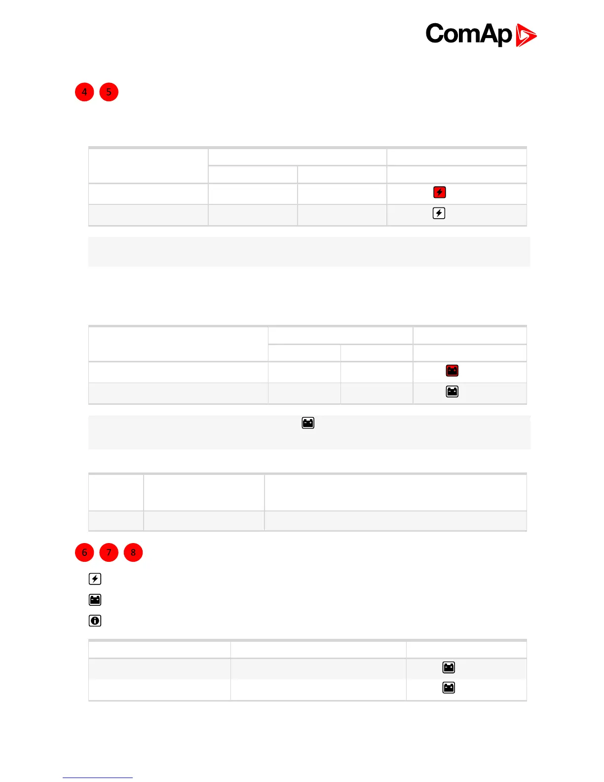
Isolated, voltage free, output contacts of mains fail alarm relay (pin 3,4 and 5) are active under AC input fail
conditions. See details in table below.
Mains fail?
Relay output pair Fail indicator
pin 3–4 pin 3–5
YES open closed
– led on
NO closed open
– led off
Note: For better system reliability set up at least 5 s input delay when signal is further processed, for example
by PLC.
Isolated, voltage free, output contacts of battery or charge fail alarm relay (pin 6,7 and 8) are active under low
battery, wrong battery connection, charging fail or battery to be replaced conditions. See details in table below.
Battery or charge fail?
Relay output pair Fail indicator
pin 6–7 pin 6–8
YES open closed
– led on
NO closed open
– led off
Note: In Recovery the Battery or charge fail indicator is OFF but the Relay is in failure mode (pin 6–8
closed) to indicate a battery with very low voltage.
Max
30 V
DC
, 1 A
60 V
AC
, 1 A
Resistive load (EN 60947-4-1)
Min 5 V
DC
, 1 mA Min. permissive load.
Relay contact rating
Status indicators
Mains fail indicator.
Battery or charge fail indicator.
Diagnostic indicator.
Charging phase Diagnostic indicator Fail indicator
Float 1 blink / 2 s
– led off
Absorption 1 blink / s
– led off