InteliCharger 240 24 Reference Guide
9
4 Charger setup and operation
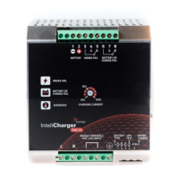
4.1 Front panel description
AC input terminal
Maximum charging current adjustment
Battery output terminal
Mains fail signal output terminal
Battery or charge fail signal output
terminal
Mains fail indicator
Battery or charge fail indicator
Diagnostic indicator
Battery type selector
Boost charge selector
Life Test function selector
4.2 Detailed description
AC input terminal
Use 3 wires connection (L - phase, N - neutral, PE - protective earth) according to description in chapter AC
input wiring diagram (page 7).
Charging current level
Using this adjusting element it is possible to set max. charging current for battery. The current adjustment goes
from 20–100 % of charger nominal current I
n
. Set the maximum charging current (in A) as 20–100 % of the
battery capacity (in Ah).
Battery output terminal
Connect the battery between pin 1 (- polarity) and pin 2 (+ polarity).
use two batteries (12 V) for 24 V charger output