Comar Condensatori Spa, Valsamoggia, Bologna, Italy
MU 02.04 Rev.10 – ed.04/18
11
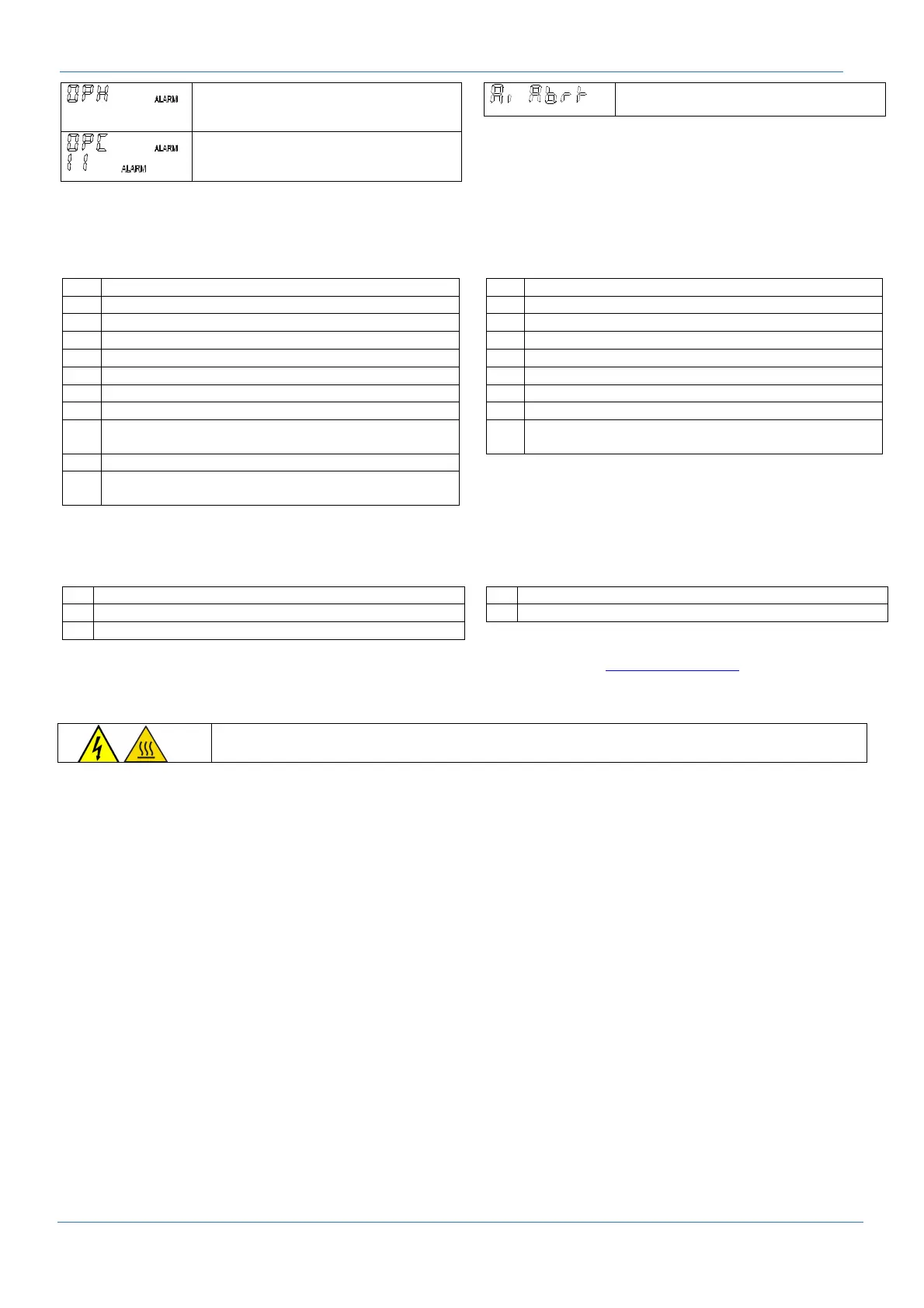
The maximum number of hours of
operation has been reached. Perform
extraordinary maintenance.
The maximum number of switching
cycles has been reached on one or more
banks.
/
Automatic initialization has been
interrupted due to poor load conditions.
When alarm conditions end, automatically normal operation condition is restored and the alarm relay is restored.
Measurements displaying
From the main menu press key ► to enter. Keys ▲ e ▼ are used to scroll measures.
U Line voltage [V]
U Phase voltage [V]
I Current measured by CT [A]
W Active power [W]
Q Reactive power [var]
∆Q Reactive power needed to reach the control target [var]
S Apparent power [VA]
THD
U
Voltage harmonic level THD%
Har
U
Voltage harmonic [%], the order of the harmonic is
indicated on the top of the display (3, 5, 7, 9, …, 19)
THD
i
Current harmonic level THD%
Har
i
Current harmonic [%], the order of the harmonic is
indicated on the top of the display (3, 5, 7, 9, …, 19)
cos φ
Measured value of cos φ on 3 digit
PF Power Factor P/S, PF ≠ cos φ
APF
Average power factor
F Line frequency [Hz]
t Temperature [°C]
thi Maximum measured temperature value [°C]
OPh
Operating hours count [h]
tan Measured value of tangent φ
hi
Maximum registered values for:
voltage, THDu
Bank parameters display
From the main menu press key ▼ until the writing INFO appears on the right side of the display. Then press key ► to enter.
Select the bank with ▲e▼ and then press ► to enter the selected bank menu.
CC
Actual power [kvar]
Percentage of nominal value [%]
OC
Number of operations
Type of bank (auto, Foff, Fon, AL, Flty)
OPh
Operating hours
For more information on the regulator, download the full user manual from the web site www.comarcond.com.
5. Maintenance
WAIT AT LEAST 20 MIN AFTER POWER DISCONNECTION BEFORE WORKING INSIDE THE
EQUIPMENT TO ALLOW COMPONENTS TO COOL AND CAPACITORS TO DISCHARGE
A proper and scheduled maintenance is needed to prevent any failure risk and to guarantee equipment expected life
Every 3 months
• Check tightening torque of all power connections (to be executed also during the commissioning).
• Check the integrity of the protection devices (fuse, varistors on thyristors,..)
• clean the cabinet, removing powders or foreign bodies particularly on top of all the components where the dust settled, becoming wet, it could
result in superficial partial discharges (busbars supporting insulator, contactors, closing plate of the capacitors, etc.)
• make sure no condensation is present on the live parts of the equipment
• Check the integrity of the insulation of the electrical cables specially close to the hot components (reactors, discharge resistors).
• Check the operation of the cooling fans and make sure that the filters are not clogged
• Verify the integrity of any surge protection devices present in the equipment
Every 6 months
• verify the correct operation of the regulator and of the contactors: in manual mode switch on each bank and verify if its contactor is properly
closing and opening.
• Check the integrity of the capacitor’s discharge resistors
• Make sure that the overpressure device of each capacitor is not activated.
• Measure the current of each bank on each phase, recording the values and comparing them with the rated ones. In case of changes bigger than
15% from rated value, you have to measure the capacitance of each capacitors, if it differ more than 15%, replace it.
• make sure the cooling system is working properly. For this purpose you can use an hot air blower to heat the control thermostat (at 35°C they
shall close and operate the fans) and the alarm thermostats (at about 55°C they shall open, opening the auxiliary circuit, disconnecting the
capacitor banks). Wait few minutes the cooling of the thermostats. Verify the recovery of the normal operation.
Every 12 months
• Check the integrity of the pre-charge resistors of the contactors (when present). When they are damaged ,replace the whole contactor.
• Verify the number of operations performed by each contactor:
BMR and HPR regulators are recording the number of operations for each capacitor bank. When the value exceeds 200 000, replace the
contactor.
• Check for oxidation and/or corrosion on each component, particularly of the copper busbars/cables and over the enclosure surfaces.
 Loading...