28
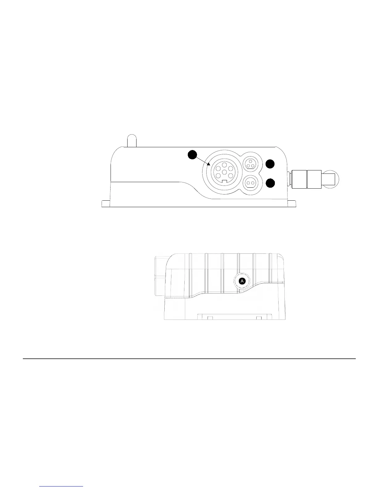
Figure 10 - Connector view of RF512, RF515, RF516 & RF542 Transmitter
A. Lumberg Socket for Probe
B. Socket for Door & RF525 Activator (Dual function)
C. External DC adaptor socket
Figure 11 - Ethernet Link Indication Window (RF542 Only)
A. Ethernet link indication (once a link is detected the green indicator will be illuminated)
C
B
A