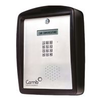
11. Remove the cover (5) from the mounting
plate (6) as follows (See Figure 17):
a. Using the 5.5 mm Alan Key
remove the four Allan Capped
screws (1 - 4).
b. Remove the housing (5) from the
mounting plate (6).
Figure 17: Remove Cover from
Mounting Plate
Screw no (3) also earths the PCB (See Figure 8).
Place the housing on a clean, dry surface to prevent water and dust
damage.
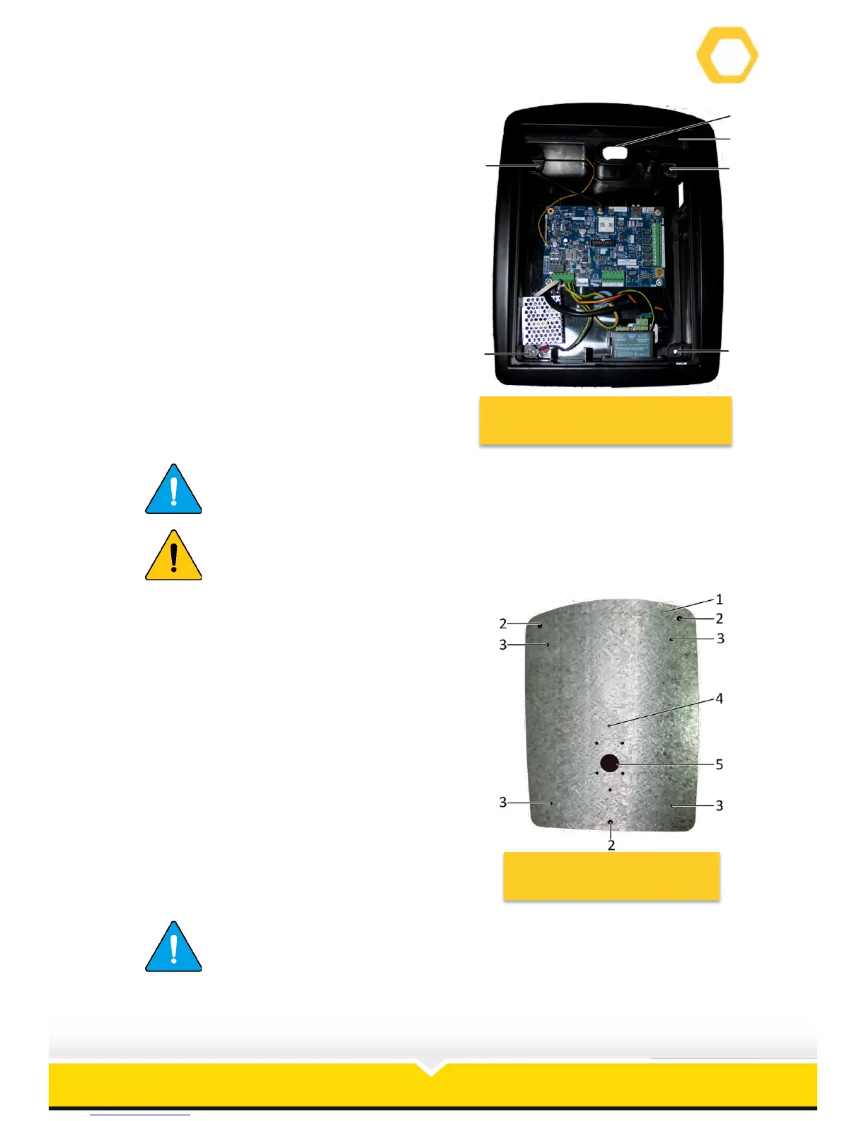
12. The mounting plate (1) has the following
holes (See Figure 18):
a. Wall mounting holes (2).
b. Cover mounting holes (3).
c. Gooseneck mounting holes (4).
d. Wiring hole (5).
13. Align the wall mounting holes with the
corresponding holes drilled in the wall.
14. Ensure that the curved end of the mounting
plate faces up.
15. Insert the three 8 mm rawl bolts and secure
the intercom mounting plate to the wall.
16. Feed the 220V supply through the centre
hole (5).
Figure 18: Mounting Plate
The screws that attaches the mounting plate to the wall is not
supplied. It is suggested that 8 mm rawl bolts are used to secure that
mounting plate.
 Loading...