EQUIPMENT MANUAL FOR SP-2110
SP-2110 QE
Copyright - refer to title page
Page 12
ENU Status : 1-3-1
2 EQUIPMENT DESCRIPTION
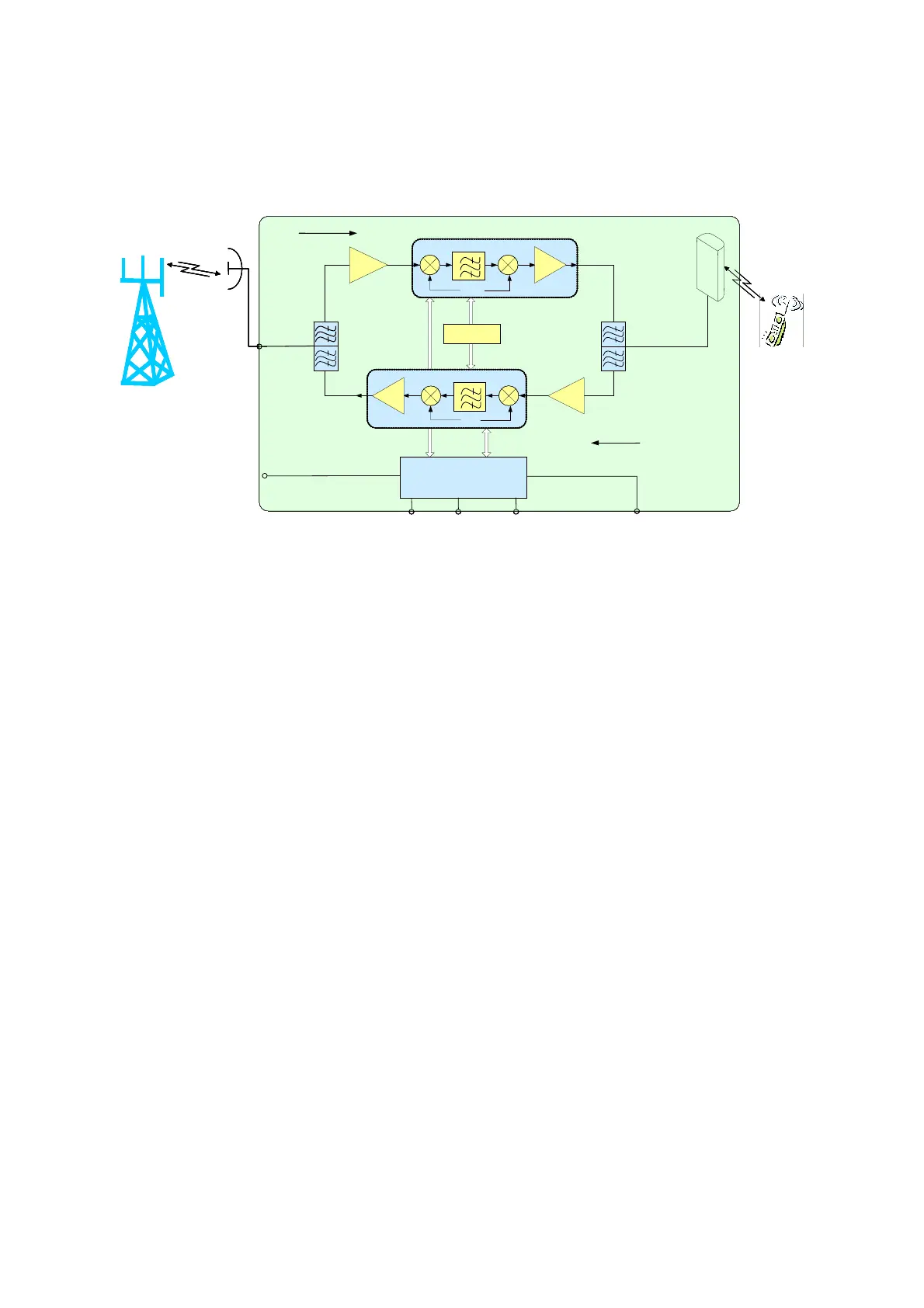
2.1 SP-2110 SYSTEM DIAGRAM
DC 6V
Down Link
Up Link
MT
DT
f
P
f
P
PA2
LNA1
PA1
LNA2
BTS
DT ANT
Internal
ANT
Mobile
Phone
MCU
PLL
LED
DC 6V
Downlink
Uplink
MT
DT
f
P
fp
PA2
LNA1
PA1
LNA2
BTS
DT ANT
Internal
ANT
Mobile
Phone
MCU
PLL
LED
DC 6V
Down Link
Up Link
MT
DT
f
P
f
P
PA2
LNA1
PA1
LNA2
BTS
DT ANT
Internal
ANT
Mobile
Phone
MCU
PLL
LED
DC 6V
Downlink
Uplink
MT
DT
f
P
fp
PA2
LNA1
PA1
LNA2
BTS
DT ANT
Internal
ANT
Mobile
Phone
MCU
PLL
LED
Fig 2: SP-2110 System diagram
As shown in the above figure, in downlink BTS signals are received by donor antenna (connected
with DT port and located outdoor). After the duplexer the signals are sent to LNA for pre-amplification,
to FSA afterwards to get required output power. Then the signals are filtered by duplexer and are sent
to service antenna (connected with MT port and located indoor) to cover the area.
In uplink the signals from subscriber’s handset are sent to the device through service antenna. After
the duplexer the signals are sent to LNA and FSA. Then after the duplexer again, the signals are sent
to BTS through donor antenna.
Note:the mobile antenna can be either the defaulted integrated antenna or the optional external
antenna according to customer’s requirements.