Contents
3
C3M2-OM-EN-02
Contents
Section 1:
Safety Information ........................................................................... 6
1.1
Safety Statements ................................................................................................... 6
1.2
Operator Safety ...................................................................................................... 6
1.3
Safety Decals ......................................................................................................... 7
1.4
Safety Equipment ................................................................................................... 8
1.5
Warning Devices .................................................................................................... 9
1.6
Operator Qualification and Responsibilities ........................................................ 10
1.7
Work Place Operating Conditions ....................................................................... 12
1.8
Diesel Particulate Filter (DPF) Regeneration ...................................................... 15
1.9
Decommissioning Recycling and Disposal ......................................................... 16
Section 2:
Basic Information .......................................................................... 17
2.1
Intended Use ........................................................................................................ 17
2.2
General ................................................................................................................. 17
2.3
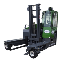
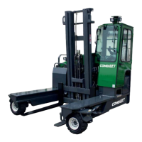
Vehicle Description ............................................................................................. 18
2.4
Principle of Operation .......................................................................................... 19
2.5
Serial Number and Serial Plate ............................................................................ 20
2.6
Rated Capacity, Centre of Gravity and Stability ................................................. 21
2.7
Load Centre & Load Chart .................................................................................. 24
2.8
Attachments ......................................................................................................... 25
2.9
Tilting ................................................................................................................... 26
Section 3:
Components & Controls ................................................................ 27
3.1
Machine Overview and Components ................................................................... 27
3.2
Operating Components & Controls ..................................................................... 28
3.2.1
Steering Wheel / Column ................................................................................. 29
3.2.2
Inch Brake Pedal .............................................................................................. 30
3.2.3
Accelerator Pedal ............................................................................................. 30
3.2.4
Operator’s Seat ................................................................................................. 30
3.2.4.1
Kab 100 Series Seat Adjustments........................................................................................................ 32
3.2.4.2
Grammer Seat Adjustments................................................................................................................. 34
3.2.5
Switches/Buttons.............................................................................................. 36
3.2.6
Switches/Buttons for Optional Extras .............................................................. 37
3.2.1
Multifunction Display Console (MDC) ........................................................... 39
3.2.7
Battery Isolator Key Switch ............................................................................. 40
3.3
Hydraulic Function Lever Operation ................................................................... 41
3.4
Hydraulic Joystick Operation (If Fitted) .............................................................. 42
Section 4:
Operation Monitoring .................................................................... 43
4.1
Daily Pre-Shift Inspection Screen ........................................................................ 43
4.2
MDC Home Screen .............................................................................................. 44
4.3
MDC Pop Up Icons .............................................................................................. 52
4.4
Miscellaneous Dash Panel Indicator Lights ......................................................... 55
4.5
MDC Engine Fault Codes .................................................................................... 56
Section 5:
Operation ........................................................................................ 57
5.1
Pre-Use Checks .................................................................................................... 57
5.2
Fuel Handling & Storage ..................................................................................... 62