10
Advanced configuration
Intercom call
Introduction
If the standard configuration settings (A-P) do not reflect requirements, the buttons can be programmed dierently by carrying
out the steps below.
After programming, set S2 DIP-switches 1-2-3-4 (PROG) to ON. With these DIP-switch settings, the buttons manage the
programmed functions.
The buttons that are NOT programmed control the functions in row A (table “Basic configuration” ).
By "General intercom call" we mean a call from a door-entry phone/door entry monitor to the devices (in the same apartment or another
apartment) identified by the call address for the apartment (user code).
By "Intercom call to selective address" we mean a call from a door-entry phone/door entry monitor to a device (or several) identified by a
specific (selective) address which is dierent from the call address for the apartment (user code).
General and selective intercom calls CANNOT be used together on the same riser!
General intercom call: button programming
1. Take note of the S1 DIP-switch settings.
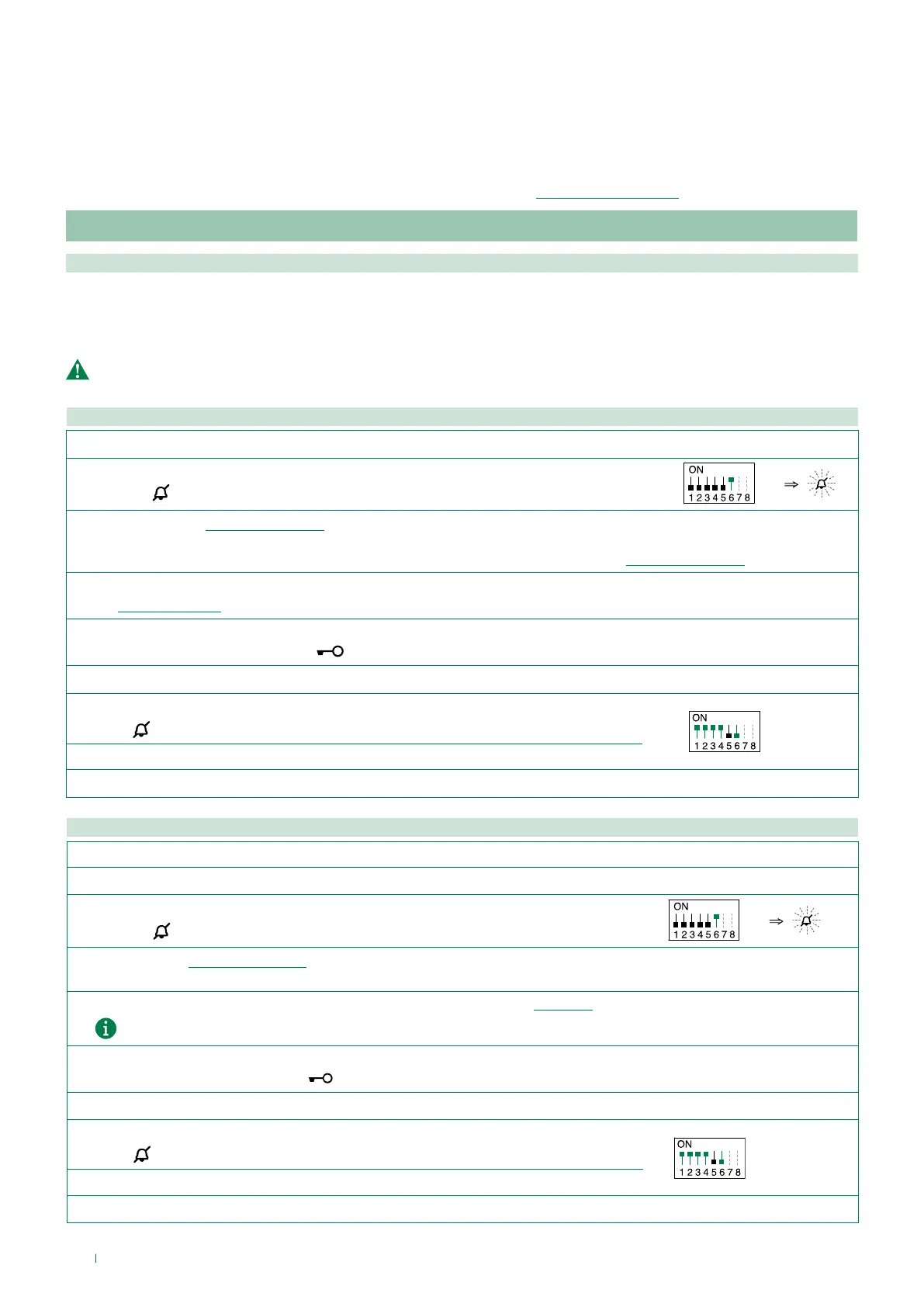
2. To enter programming mode, set S2 DIP-switch 6 to ON.
» the LED
flashes
S2
3.
Refer to the table “Basic configuration” to identify a DIP-switch combination in which the intercom function (INT or INTb) corresponding to
the button you want to program appears, then set the S2 DIP-switches.
Example: For button 1= Intercom (INT) set S2 DIP-switches 1-2-3-4 as specified in row "C" in the table“Basic configuration”
4.
Set the S1 DIP-switches according to the call address of the desired apartment.
See “Addressing table”
5. Press and release the button to be associated with the function.
» Correct procedure indication: the LED
flashes for a few seconds and a confirmation tone sounds.
√ When programming using several buttons, continue programming the next key by repeating the process from step 4 onwards.
6.
Exit programming mode by setting S2 DIP 6 to OFF.
» LED
switches off
S2
7. Set S2 DIP-switches 1-2-3-4 to ON.
8. Return S1 DIP to the original combination.
Intercom call to selective address: button programming
1. The steps illustrated in paragraph “Assigning a selective address” should be carried out on the devices involved in the intercom call.
2.
Take note of the S1 DIP-switch settings.
3.
Exit programming mode by setting S2 DIP 6 to OFF.
» the LED
flashes
S2
4.
Refer to the table “Basic configuration” to identify a DIP-switch combination in which the intercom function (INT or INTb)
corresponding to the button you want to program appears, then set the S2 DIP-switches.
5. Use the S1 DIP-switches to set the selective address of the device you wish to call. “TABLE B”.
For group calls, simultaneously set the desired selective addresses (max. 3) to ON.
6. Press and release the button to be associated with the function.
» Correct procedure indication: the LED
flashes for a few seconds and a confirmation tone sounds.
√ When programming using several buttons, continue programming the next key by repeating the process from step 5 onwards.
7.
Exit programming mode by setting
S2 DIP-switch 6 to OFF.
» LED
switches off
S2
8. Set S2 DIP 1-2-3-4 to ON.
9. Return S1 DIP to the original combination.