11
Selective intercom address
Assigning selective address
(Steps only need to be carried out for “Intercom call to selective address” programming)
1. 2. 3. 4.
Take note of the
S1, S2 settings and
restore them when
programming is
complete.
S1: Set an address.
(“TABLE B”)
Example: 3
S1
S2: Set the DIP-switches as
shown in the figure.
S2
Assign one of the 8 addresses available in “TABLE B” to each device involved in the intercom call.
• You can assign the same selective intercom address to a maximum of 3 devices.
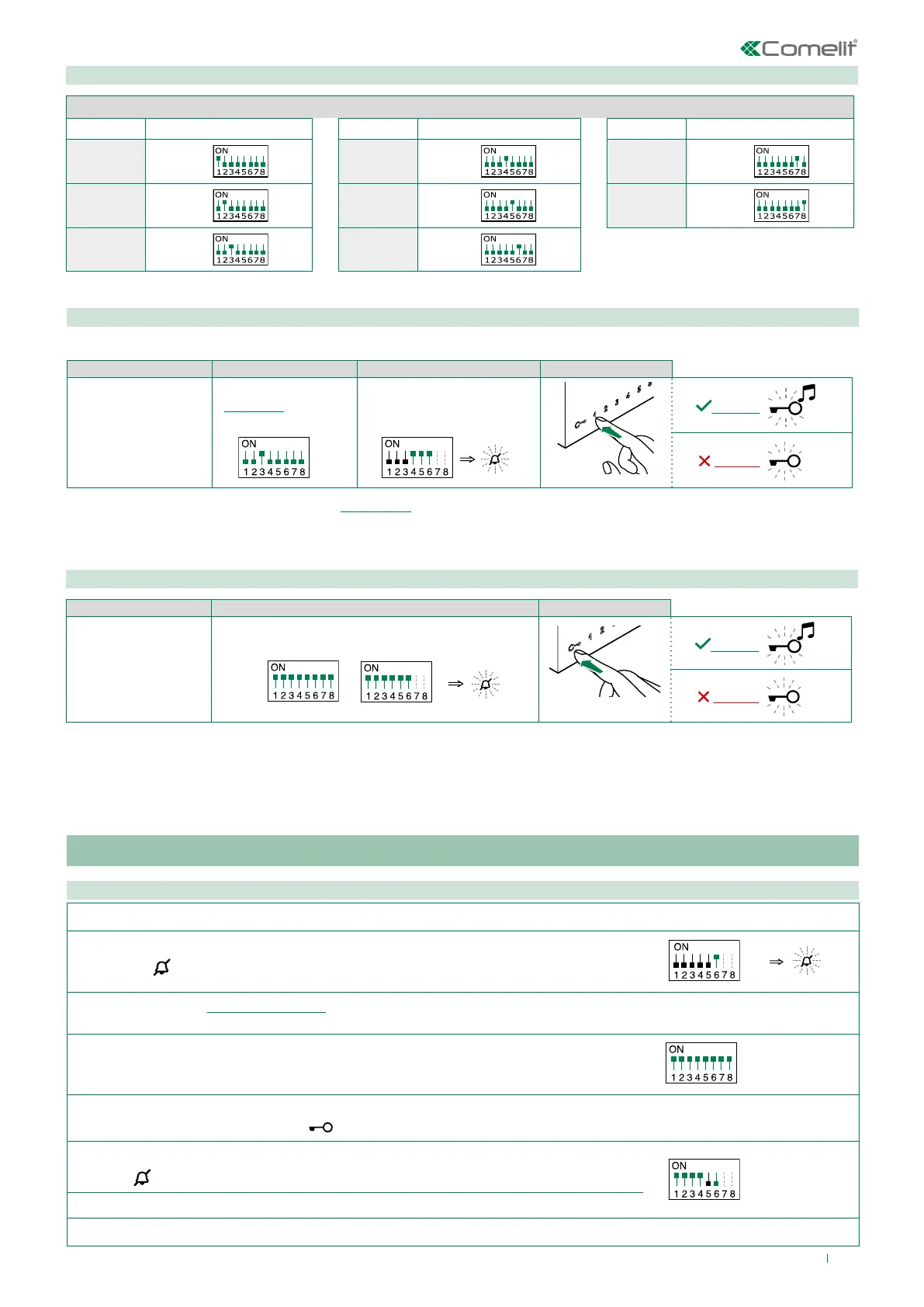
TABLE B
Code S1 DIP-switch ON Code S1 DIP-switch ON Code S1 DIP-switch ON
1 1 4 4 7 7
2 2 5 5 8 8
3 3 6 6
Deleting the selective address of the door entry monitor
1. 2. 3.
Take note of the
S1, S2 settings and
restore them when
programming is
complete.
Set the DIP-switches as shown in the figure.
S1
S2
Generic actuator, coded actuator
Generic actuator: button programming
1. Take note of the S1 DIP-switch settings.
2.
Exit programming mode by setting S2 DIP 6 to OFF.
» the LED
flashes
S2
3.
Refer to the table “Basic configuration” to identify a DIP-switch combination in which the actuator function (ACT) corresponding to the
button you want to program appears, then set the S2 DIP-switches.
4. Set all S1 DIP-switches to ON.
S1
5. Press and release the button to be associated with the function.
» Correct procedure indication: the LED
flashes for a few seconds and a confirmation tone sounds.
6.
Exit programming mode by setting
S2 DIP-switch 6 to OFF.
» LED
switches off
S2
7. Set S2 DIP-switches 1-2-3-4 to ON.
8. Return S1 DIP-switches to the original combination.