4
Safety
Product description
Installation
Safety instructions
Make sure that any person installing, taking into operation
and operating the Buchholz relay:
• Is technically qualied and competent.
• Fully comply with these assembling instructions.
Improper operations or misuse could cause danger to:
• life and limb.
• to the equipment and other assets of the operator.
• to the equipment proper function.
Opening of the device will void your warranty.
Safety instructions in this manual are shown in three diffe-
rent forms to emphasize important information.
Safety notes on the equipment operation
Electrical installation is subject to the relevant national
safety rules.
It is mandatory to connect the grounding cable because of
safety reason.
This information indicates particular danger to life and health.
Disregarding such a warning can lead to serious or fatal injury.
It is important to observe the limit values indicated on
the nameplate and in the operating instruction before
commissioning the device.
All relevant fire protection regulations must be strictly followed.
This information indicates particular danger to equipment or
other property of the user. Serious or fatal injury cannot be
excluded.
Installation, electrical connection and fitting the device may only
be performed by qualified personnel and only in accordance
with this instruction manual.
It is the responsibility of the user to ensure that the device is
used for specified application only.
For safety reasons, please avoid any unauthorized and improper
usage.
This notes give important or specific information concerning the
equipment or as to work with the equipment.
The pipe from the relay to the oil conservator must be placed with a
n inclination to ensure free escape of switching gas.
COMEM recommends an angle of 2.5 Degree from the horizontal
(at maximum 5 degree).
Install the relay in a place where the influence of magnetic fields is
felt as little as possible.
WARNING
WARNING
WARNING
CAUTION
CAUTION
NOTE
NOTE
NOTE
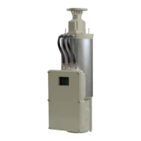
The relay Buchholz relay is used for railway application.
The BR 25 relay is located in the pipework between
the transformer and its conservator; during normal tran-
sformer operation it is lled with oil .
When the gas is generated in the transformer, it rises
towards the conservator and collects in the upper cham-
ber of the relay.
The oil level goes down and the upper oat activates the
alarm switch.
Moreover this relay operates in case of abnormal oil ow
from the transformer tank to the conservator. If it happens
the ow vent moves the support of magnets that switches
the trip reeds.
Assembly
Mechanical test
Unscrew the plug (Fig.1/A) then slowly push the button
(Fig.1/B) following the red arrow as per gure below. In
this way the oats moved and the switches activate.
The button, after been quickly released (without accom-
pany it), automatically comes back to original position.
Once the verication has been completed, t and tighten
the cap nut. This test does not give the conformity of the
electrical scheme.
BR 25 FOR RAILWAY APPLICATION
Install the relay in the pipe that goes from the on-load
tap-changer tank to oil conservator, in an horizontal posi-
tion and with the test button upwards.
The red arrow on the relay must point towards the con-
servator.
Use a pipe diameter of at least 25 mm nominal diameter.
The relay should protected against vibrations. Between the
relay and the pipe anges, install the plane gasket (please
note that is not included with the device).
Provide a stop valve between the relay and the conservator.