5
Operation and
maintenance
Maintenance
During regular check of the transformer, we recommend
performing the following checks on the BR 25 for railway
application:
• Check the exterior condition of the device.
• Verify the switches functioning following the chapter 3.2
(Mechanical test)
• Check the gaskets condition and if any leakage exists.
Storage
The BR 25 storage has to be done in its packaging, in dry
place with temperature in the range -10°C ÷ +40°C.
Upon receiving the BR 25, please check:
• The outer surface of the packaging to check that it is
intact;
• That there are no breakages.
If damages are found, please contact COMEM, reporting
the data provided in the delivery note and the serial num-
ber of the BR 25.
Figure 1
Figure 2
Figure 3
B
A
C
D
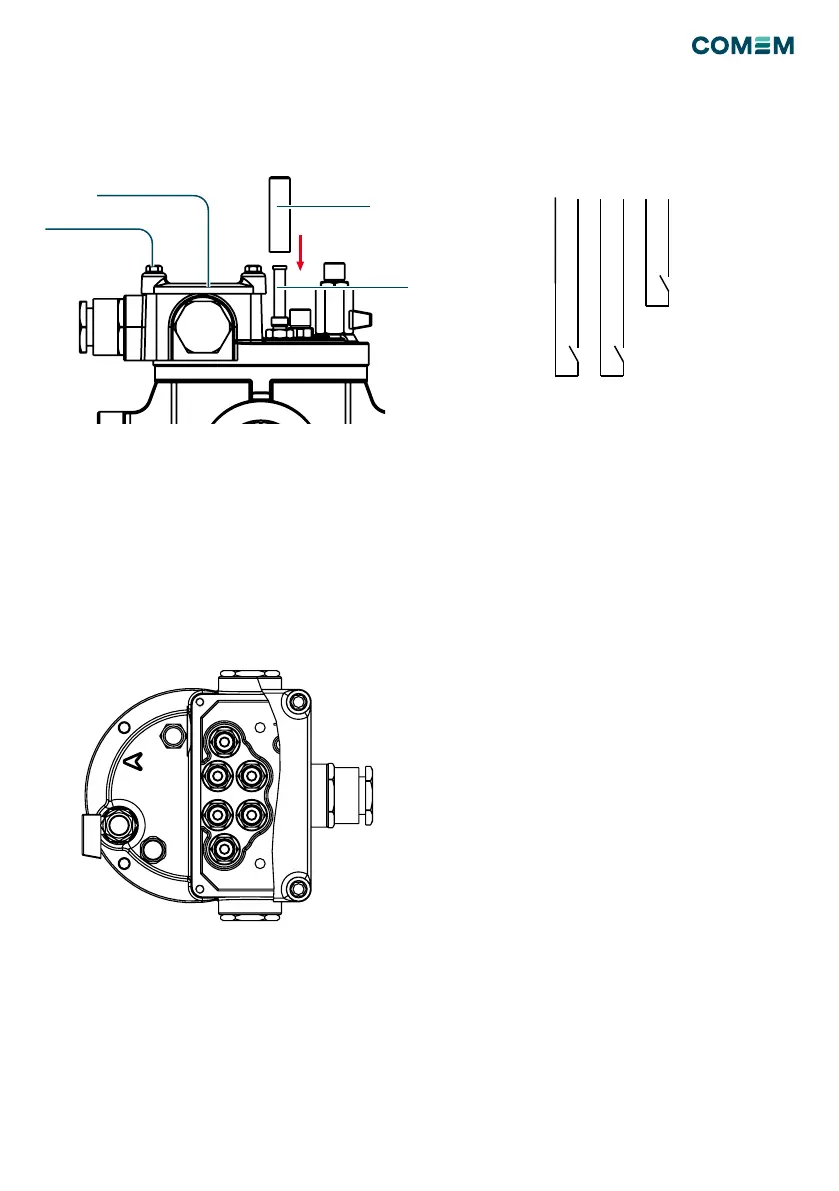
Remove the terminal box cover (1/C) unscrewing
the four M5 screws (1/D). Enter the wire through the
cable gland.
Connect the leads (terminal bolts M6, max torque 2 Nm)
following the electrical scheme reported on the label.
Connect the earth conductor to the ground screw M4 in
the terminal box (max torque: 5 Nm).
Re-close the terminal box: during this operation check the
gasket, the surface must be clean.
Diagram type CC
Electrical connection
DIAGRAM TYPE A
1
2 3 4
Trip circuit
Alarm circuit
DIAGRAM TYPE L
DIAGRAM TYPE P
DIAGRAM TYPE G
Alarm circuit
Alarm circuit
Trip circuit
Trip circuit
Trip circuit
1 2 C1 43 C2
1 2
C1 43C2
Alarm circuit
1
C1
4
3
C2 2
In case of trip switching by the ow valve (increased uid
speed) it is necessary to operate on the mechanical test
push button following the previous indication.
This operation is necessary to rearm the ow valve on the
normal working position.