Shenzhen Comen Medical Instruments co., ltd.
11
Chapter 3 Principle introduction
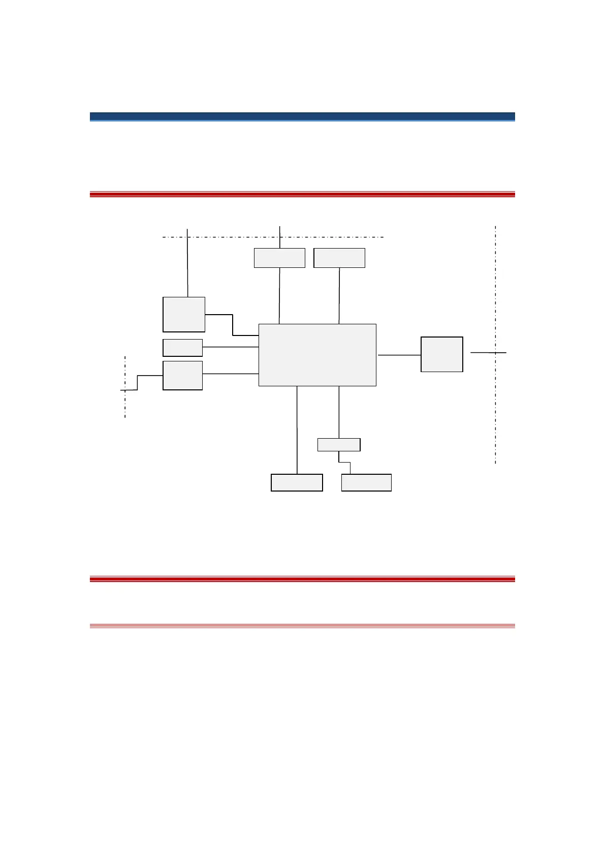
3.1 CM300 system principle block diagram
3.2 CM300 Module Introduction
3.2.1 Main board (2410 core board + CM300 bottom board)
The main board is the heart of the instrument. It consists of bottom board and core board (CPU
board), it implements a series of tasks including CPU system, display processing, printing control,
keyboard signal processing. CPU system receives electrocardiogram signal that collects by ECG
board, and send to recorder after printing control system. CPU system receives also signals from
button board to finish the button board signal process, moreover, signals of lead-fall, paper
detecting, battery management are all processed by main board CPU. The main board also
process print task, CPU system receives order and data from print control system, generate
control signals for stepping motor and printer head to implements waveforms and other
information’s print. CPU system also sends order and data to display waveforms and other