3
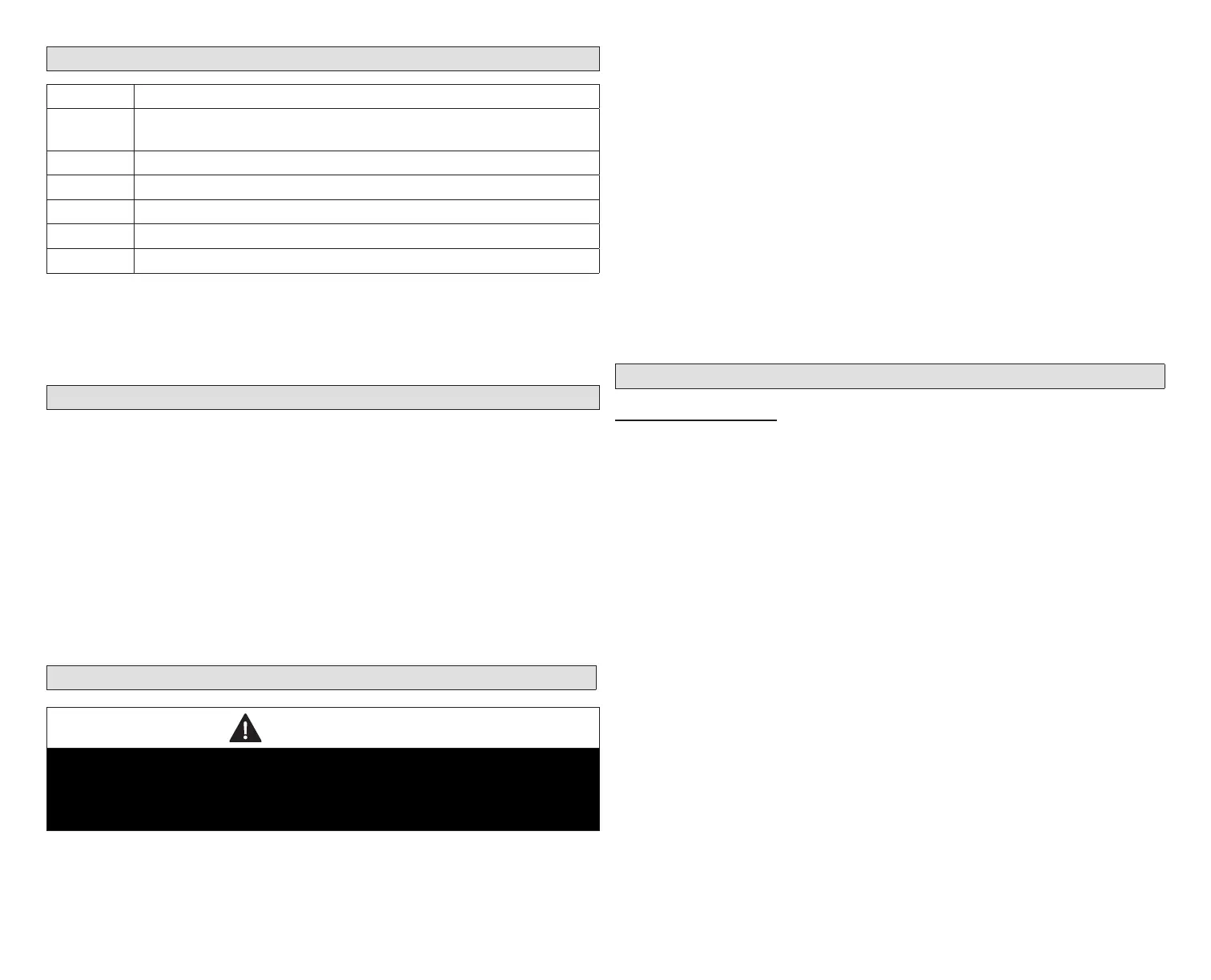
Shipping and Packing List
Quantity Description
1
Comfort Sync A3 ultra smart thermostat includes a Smart Hub
and HD Display
4 Mounting screws (#6 X 1.25” pan head)
4 Wall anchors (alligator anged solid wall anchors)
1 Installation and setup guide
1 User guide
1 Warranty certicate
NOTE: Due to Allied Air’s ongoing commitment to quality, features and options
are subject to change without notice and without incurring liability.
Improper installation, adjustment, alteration, service or maintenance
can cause property damage or personal injury. Installation and service
must be performed by a qualied installer and servicing agency.
Operating and Storage Environment, Electrical and Dimensions
• Operating Temperature is 32°F to 104°F (0 to 40°C)
• Shipping and storage temperature range is -4°F to 140°F (-20°C to 60°C)
• Operating humidity range is 10% to 90% non-condensing at 104°F (40°C)
• Storage humidity range is 5% to 95% non-condensing at 104°F (40°C)
• Comfort Sync A3 Smart Hub Power Input: 24VAC, 1AMP at 60Hz.
• Comfort Sync A3 Smart Hub DC Power Output: 12VDC (to HD Display)
• Dimensions (H x W x D):
» HD Display: 7-1/4” x 5” x 1” (184 x 122.5 x 23 mm)
» Comfort Sync A3 Smart Hub: 4-1/2 x 4-/2 x 1-1/2” (114 x 114 x 38 mm) -
antenna length is 7-1/4” (184 mm)
Installation Recommendations
WARNING
Improper installation, adjustment, alteration, ser vice or maintenance can
cause property damage, personal injury or loss of life.
Installation and service must be performed by a li censed professional HVAC
installer (or equivalent) or a service agency.
Before beginning installation, note the type of equipment, number of stages,
and any accessories being installed.
Do
• Read this entire document, noting which procedures pertain to your specic
equipment and system requirements.
• Make sure that all wiring conforms to local and national building and electrical
codes and ordinances.
Do Not
• Install on voltages higher than 30VAC.
• Short (jumper) across terminals on the gas valve or at the system controls
to test installation. This will damage the thermostat and void the warranty.
• Exceed 300 feet (91 meters) run when using 18AWG or 22AWG thermostat
wire or larger (shielded or unshielded).
• Allow power load from any thermostat connection to be more than 1 AMP.
Smart Hub Installation, External Components, LEDs and Terminals
Smart Hub InStallatIon
1. Things to consider when installing the Smart Hub:
• Install near the indoor unit such that there is a direct path to the
approximate location of the home Wi-Fi access point (the signal is not
blocked by the indoor unit or duct work, for example).
• Can be attached to a vertical surface such as a wall stud or roof truss
web, or to a horizontal surface such as a oor or ceiling joist, or a roof
rafter.
• Smart Hub antenna should be positioned such that it is roughly vertical,
no matter the orientation of the Smart Hub itself.
• Do not install the Smart Hub on the indoor unit, duct work, or other
equipment that could induce vibration in the Smart Hub.
• Do not install the Smart Hub on or near large metal objects. This could
adversely affect the range and directional coverage of the Smart Hub
Wi-Fi signal.
• If the Smart Hub MUST be installed on a metal object, orientate the
antenna perpendicular to the metal surface.
• In all cases, the Smart Hub antenna orientation may need to be
adjusted to obtain best Wi-Fi results.
2. Use the procedure outlined in “Figure 1. Smart Hub Installation” on page
4 to install the Smart Hub controller.