9
WIrIng DIagramS
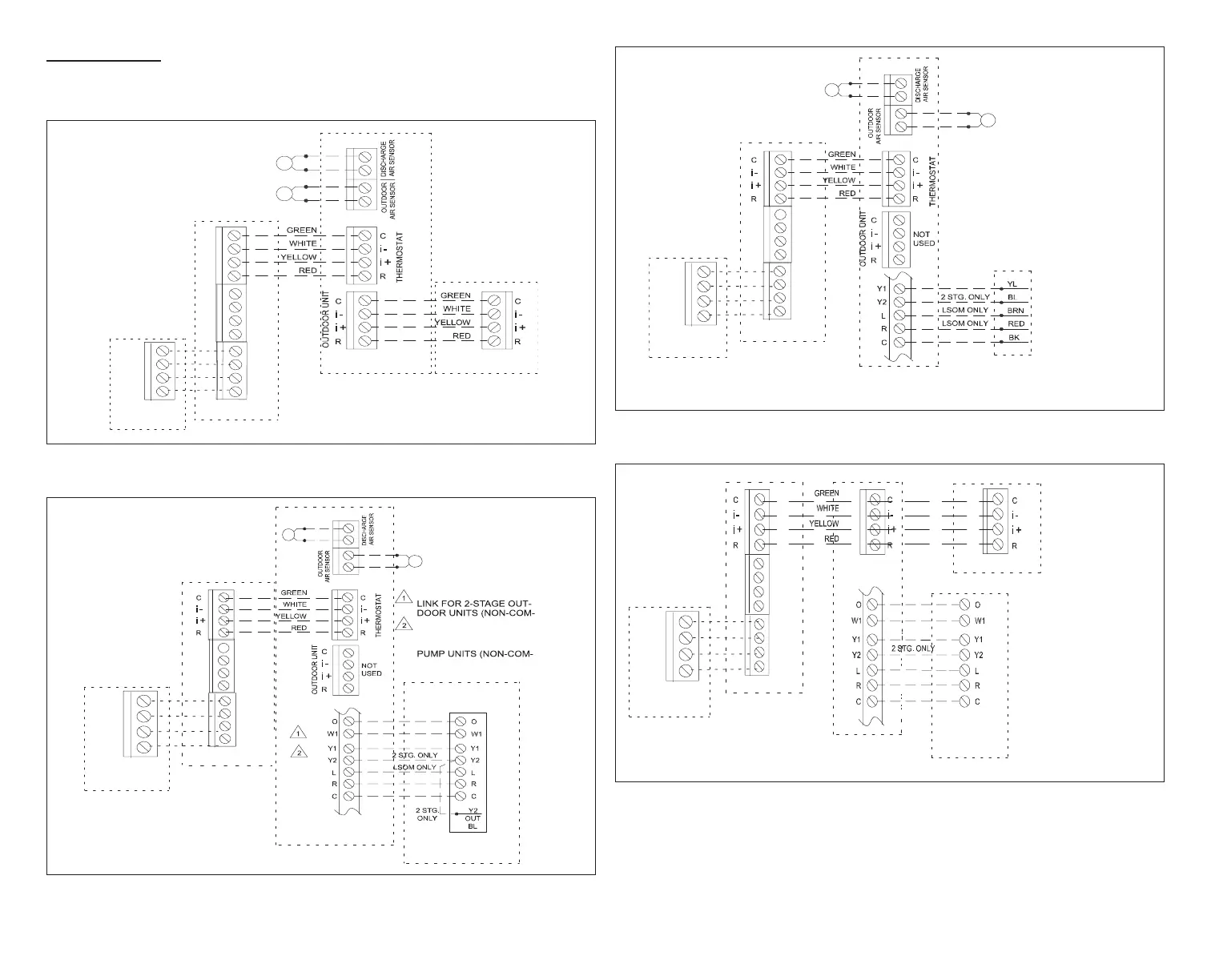
The following diagrams are typical low voltage wiring connections for various
system congurations.
Communicating
Indoor Unit
Smart Hub
C
i+
i-
R
HD
Display
Subbase
-
COMMBUS
A B
ACC1 ACC2
Communicating
Outdoor Unit
OATS (Optional)
DATS (Optional)
+
B
A
+
-
Figure 5. Comfort Sync A3 with Allied Air Communicating Indoor and
Outdoor Units
24VAC 1- or 2-Stage
Heat Pump
SETUP NOTES:
CUT Y1-Y2 ON-BOARD
MUNICATING)
CUT R-O ON-BOARD LINK
FOR OUTDOOR HEAT
MUNICATING)
ACC1
ACC2
DATS (Optional)
OATS (Optional)
Smart Hub
Communicating
Air Handler Unit
-
COMMBUS
A B
+
HD
Display
Subbase
B
A
+
-
Figure 6. Comfort Sync A3, Allied Air Communicating Air Handler with
24VAC 1 or 2-Stage Heat Pump
24VAC Outdoor Unit
(1 - or 2-Stage
Air Conditioner)
SETUP NOTE:
CUT Y1-Y2 ON-BOARD LINK FOR
2-STAGE OUTDOOR UNITS
(NON-COMMUNICATING)
ACC1
ACC2
DATS (Optional)
OATS (Optional)
Smart Hub
Communicating
Indoor Unit
-
COMMBUS
A B
+
HD
Display
Subbase
B
A
+
-
Figure 7. Comfort Sync A3, Allied Air Communicating Indoor Unit with
24VAC Air Conditioner
24VAC
1- or 2-Stage
Non-Communicating
Indoor Unit
If jumber is present between
R and W2 on indoor unit terminals then
removed it. Installed jumper
may cause erroneous Alert Code 125.
ACC1
ACC2
Smart Hub
Equipment
Interface Module
Communicating
Outdoor Unit
-
COMMBUS
A B
+
HD
Display
Subbase
B
A
+
-
Figure 8. Comfort Sync A3 with Equipment Interface Module (EIM),
24VAC Indoor Unit and Allied Air Communicating Outdoor Unit


 To Next Page