4
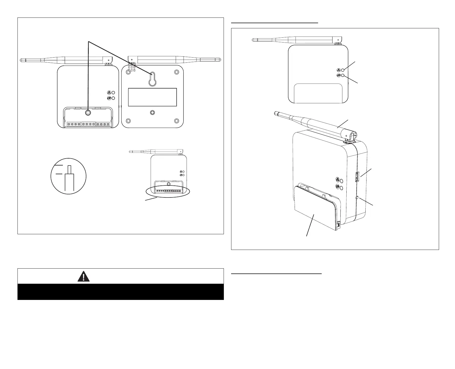
1/4”
STRIP 1/4” INSULATION FROM
END OF EACH CONTROL WIRE
A
B
D
USE SMART HUB AS TEMPLATE TO MARK DESIRED MOUNTING
LOCATIONS ON WALL OR STUD.
CAUTION: DO NOT OVERTIGHTEN LOWER MOUNTING SCREW, MAY
DAMAGE SMART HUB.
SECURE SMART-HUB TO
WALL WITH
FIELD-PROVIDED
FASTENERS
RAER
TNORF
KEYHOLE
THROUGH-HOLE
C
MAKE CONNECTIONS TO SMART HUB
SCREW TERMINALS USING WIRING
DIAGRAMS PROVIDED
TERMINALS
(screw type)
+
-
COMMBUS
A B
R i+ I- C
ACC1 ACC2
+
-
COMMBUS
A B
R i+ I- C
ACC1 ACC2
Figure 1. Smart Hub Installation
3. For low voltage wiring connections use diagrams in section titled
“Connecting Low Voltage Wiring” on page 8.
IMPORTANT
Do not install smart hub in location were direct exposure to condensation or
dripping water is possible.
Smart Hub ExtErnal ComponEntS
System Status LED
System Commissioning
Status LED
USB Port
Manual Reboot Button
Terminal Connection Access Cover
Antenna
Figure 2. Smart Hub Indicators and External Components
Smart Hub puSH button FunCtIonS
The Smart Hub push button is for rebooting. Press and hold the button for ve
seconds to reboot the Smart Hub.
The push button has a LED associated with it that indicates the status of the
Smart Hub commissioning state (see “Table 1. System Status LED Indicators”).