7
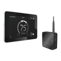
6. Use a level to align either the subbase on wall horizontally.
7. Use the subbase as a template to mark the desired mounting hole locations
on the wall.
Use the subbase as a template to
mark the desired mounting hole
locations on the wall.
HD Display Subbase
(Rear View)
8. Drill 3/16” (5 mm) holes at marked locations on the wall for anchors. Then
insert wall anchors into holes until ush with the wall.
Drill Holes
Insert in hole until flush with wall.
WARNING
DO NOT over-tighten mounting screws. Doing so my distort the subbase
plastic housing and cause connection issues when attaching the HD display.
9. Secure subbase with provided #6 x 1.25” pan-head screws (4).
10. Connect thermostat wiring to subbase screw terminals referencing
provided wiring diagrams in this guide.
HD DISplay attaCHmEnt
1. Hold the HD Display by the edges, line it up with the subbase (horizontal
position), and move the HD Display toward the subbase.
2. Center the cavity on the back of the display over the subbase.
3. Gently press on the edges of the HD Display until you hear the mounting
snaps engage. Be careful not to apply force directly on the glass.
NOTE: Once the HD Display is connected, it may take up to 45 seconds for it
to power up.
4. To remove the HD Display from the subbase, grasp the left and right edges
of the HD Display and gently pull towards yourself.
NOTE: If the HD Display is removed from the subbase base, the HD Display
will shut down and will not be able to communicate with the system.
System can be controlled from mobile devices or consumer web
portals once registration has been completed.
5. Do not remove the label covering the HD Display screen until after power
is applied to the system.
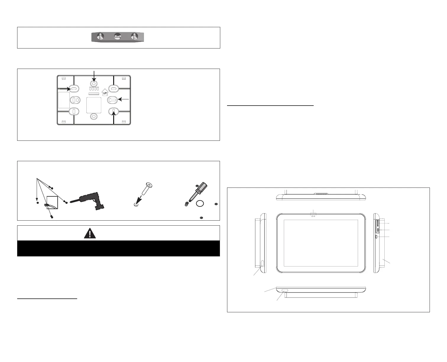
HD DISplay ExtErnal ComponEntS
• Proximity sensor - Detects a person approaching the HD Display. If the
HD Display is in Screen Saver mode and the Proximity Sensor setting is
enabled, the proximity sensor takes the HD Display out of screen saver mode
automatically and returns to the home screen when someone approaches.
• Humidity sensor - This is the intake location for the humidity sensor. Do not
block.
• Power button - Turns off the HD Display when pressed and held for about
ve (5) seconds.
• microSD card slot - Not functional, for future use.
• Micro USB connector - Not functional, for future use.
Proximity and Ambient Light Sensors
microSD slot
micro USB port
power button
humidity sensor
humidity sensor
air discharge
temperatur sensor
Subbase attached
Figure 3. HD Display Components