8
HD DISplay tErmInalS
Table 4. Smart Hub Terminal Designations and Order
Terminal Designation Description
12+ 12VDC output
A Communications bus A
B Communications bus B
12- 12VDC return
Connecting Low Voltage Wiring
The following diagrams in this section illustrates the basic Allied Air control
wiring for all compatible components.
Control WIrIng rEquIrEmEntS
The following is the wiring specication requirements for installation of this
system.
• Comfort Sync A3 wiring size is 18# AWG.
• Maximum total length of all connections combined is 1500 feet (457 meters).
• Maximum length between components is 300 feet (90 meters).
DISCHargE aIr tEmpEraturE SEnSor (DatS) (optIonal For InDoor unIt)
Installation of discharge air temperature sensor (DATS) (88K38) must comply
with the following requirements:
• Installed downstream of the heat exchanger or electric heat elements.
• It must be placed in free airow, where other accessories (such as humidiers,
UV lights, etc.) will not interfere with its accuracy.
• Wiring distance between the integrated furnace and air handler controls or
damper control module and the discharge air sensor must not exceed 10 feet
(3 meters) when wired with 18# AWG thermostat wire.
• DATS is highly recommended for all systems that include a variable capacity
outdoor unit in order to provided more precise dehumidication operation.
outDoor aIr tEmpEraturE SEnSor (oatS)
The optional outdoor air (temperature) sensor (OAS) (X2658) wiring distance to
the Comfort Sync A3 should not exceed 150 feet (45 meters) when wired with
minimum 22 #AWG (recommend 18 #AWG) dedicated 2-conductor thermostat
cable or two wire shielded. Installation of OAS must comply with the following
requirements:
• Sensor wiring must be run to avoid touching or being close to high voltage
wiring and light ballast.
• Choose a protected outdoor location away from direct sunlight or other heat
sources (usually on the north side of the building).
• Ensure that water will neither collect on, nor wash over the sensor.
• Do not locate the sensor near driveways or similar heat-absorbing masses
which may reect stored heat energy onto the sensor and send inaccurate
information to the thermostat.
• Locate the sensor away from attic and soft vents, or furnace venting pipes.
• Do not locate the sensor directly above an air conditioner or heat pump.
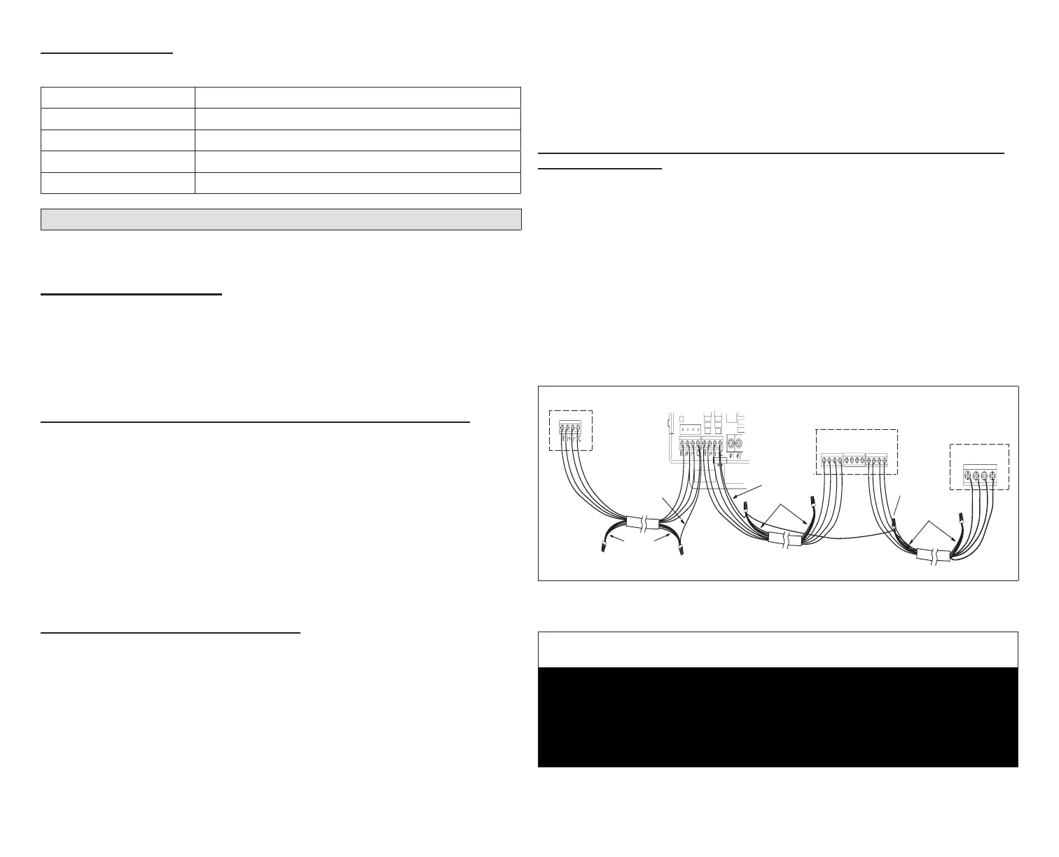
rEDuCIng ElECtrICal noISE on CommunICatIon buS - InDoor, outDoor, HD DIS-
play anD Smart Hub.
Communicating systems requires four thermostat wires between the HD
Display and Smart Hub. Four wires are also used between the Smart Hub and
indoor/outdoor units as well. When a thermostat cable with more than four
wires is used, the extra wires must be properly connected to avoid electrical
noise. The wires must not be left disconnected.
• Use wire nuts to bundle the unused wires at each end of the cable. A single
wire should then be connected to the indoor unit end of the wire bundle
and attached to the “C” terminals as shown in “Figure 4. Thermostat Wire
Termination in Communicating Systems (Electrical Noise)”.
• Keep all communication wiring as far away from the house electrical wiring
and large electrical appliances as possible. Recommended minimal distance
is 15 feet (4.6 meters).
Unused wires
Unused wires
Single wire
to bundle
wire to indoor
terminal “C”.
Single wire
to indoor unit
terminal “C”.
Unused wires
Single wire
to terminal “C”.
Indoor Unit Controller
Outdoor Unit
+12V A B
HD Display
Subbase
-12V
12VDC
12+
COMBUS
A B
Smart Hub
R i+ I- C
ACC1 ACC2
12-
Figure 4. Wire Termination in Communicating Systems
(Electrical Noise) - Typical
IMPORTANT
It is recommended to use 2-pair, 18AWG unshielded thermostat cable (eld-
provided) for power terminals (R, C, 12+ AND 12-). Recommend using 2-pair
22AWG shielded thermostat cable for communications terminals (I+, I-, A
and B) which will help eliminate any noise interference. See “Table 3. Smart
Hub Terminal Designations, Order and Wiring Requirements” on page 6
for further details.