#20379_L
US customer support 1-888-622-2377 | www.commandaccess.com | CA customer support 1-855-823-3002
7
14
After verifying the correct screw hole location, add the provided Cable Tie to the Rear Mounting
Bracket as shown and tighten the back two screws.
Then ensure the Screws holding down the Scissor Bracket are still angled correctly and the MLRK1
is sitting ush against the Base Rail. Once the MLRK1 is in place, rotate the Scissor Bracket until its
Screws stop against the cut outouts as shown, then tighten the Screws.
15
If you are installing the MLRK1 into a Jackson series device:
• Use the Front screw hole locations on the Rear Mounting Bracket and align with the front holes
on the Base Rail.
If you are installing the MLRK1 into a Kawneer or AHT series device:
• Use the Back screw hole locations on the Rear Mounting Bracket and align with the back holes
on the Base Rail.
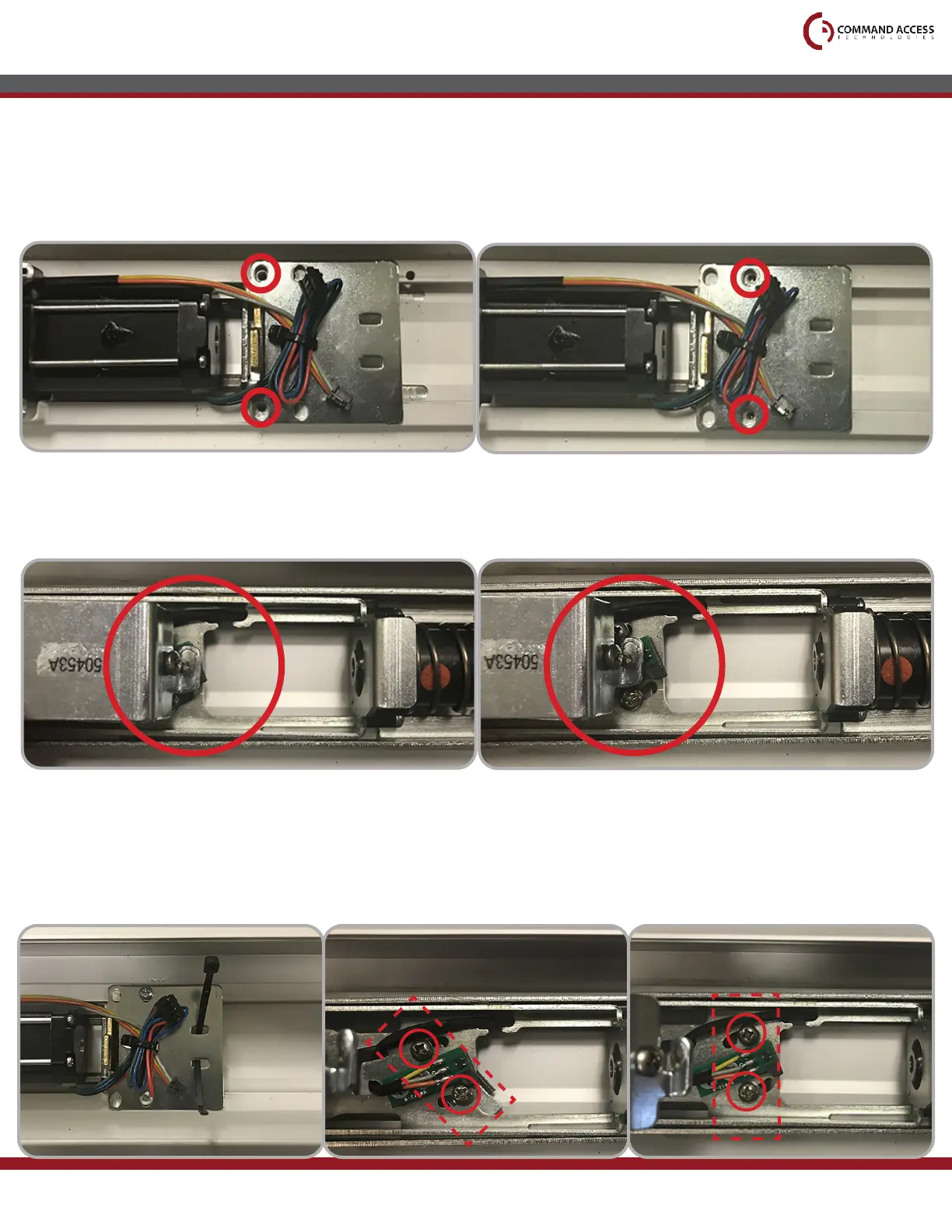
installation instructions
To verify you have used the correct hole locations, temporarily install the two provided screws into the
Rear Mounting Bracket. Then press down the Front Activating Bracket and comprae how it lines up
with the Green Sensor Board to the pictures shown below.
CORRECT INCORRECT
Before tightening After tightening