FIGURE 4 Complete the Setup Wizard to set up your Unleashed
network
5. Once the Setup Wizard is
nished, a “Conguring system sengs and
reboong” progress screen appears. Wait unl the process is
complete.
6. Connect to the WLAN that you congured in the Setup Wizard, and
click OK to reconnect. You will be redirected to the Unleashed login
screen.
7. Enter your Admin Name and Password to login.
FIGURE 5 The Login page
8. Upon successful login you will be presented with the Unleashed
Dashboard, which displays an overview of your Ruckus Unleashed
network.
Mounng Instrucons
Connecng and Sealing the RJ-45 Cables
WARNING! Do not use any PoE injector not tested and approved by
RUCKUS to power the T350c Access Point.
FIGURE 6 T350c LEDs and Ports
1. Feed the end of the cable through the sealing nut, rubber O-ring,
clamping ring assembly, and cable gland base, as shown in Figure 7.
NOTE: Do not seat the clamping ring and rubber O-ring into the
gland body unl the gland body has been torqued to
specicaons.
FIGURE 7 RJ-45 Cable and Gland Assembly
1. Cable gland base
2. Clamping ring
3. Rubber O-ring
4. Sealing nut
2. Use a wide at-blade screwdriver to remove the required (PoE IN)
blanking cap from the AP.
3. Connect the cable to the Ethernet port on the AP.
4. Tighten the cable gland base into the AP chassis to 7 N.m or 62 in-lbs.
5. Wrap the clamping ring assembly around the rubber O-ring. Make
sure that the clamping ring assembly fully encloses the rubber O-ring.
6. Seat the clamping ring assembly and rubber O-ring in the cable gland
base.
7. Hand-ghten the sealing nut.
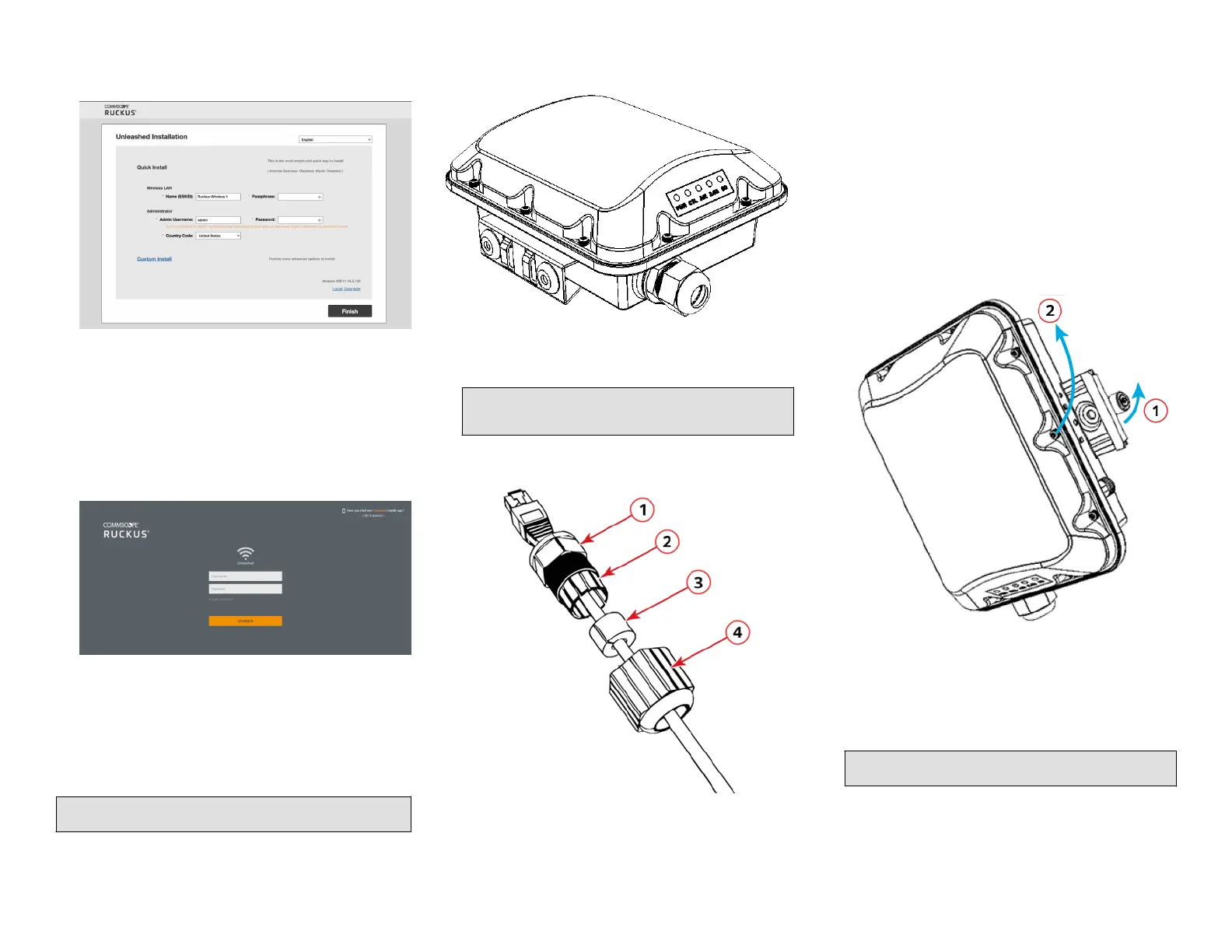
Aaching the Mounng Bracket to a Flat Surface
1. The AP mounng bracket aaches to the AP using a capve screw.
Use a medium at-blade or No. 2 Phillips screwdriver to loosen the
capve screw, as shown in Figure 8, and pull up on the end of the
bracket to remove the bracket from the AP, as shown in Figure 8.
FIGURE 8 Removing the Mounng Bracket
1. Loosen the capve
screw
2. Pull up on the end of the
bracket
2. Using either of the two opons shown in Figure 9, hold the mounng
bracket at the locaon on the mounng surface where you want to
mount the AP. Use the holes on the mounng bracket as a template
to mark the locaons of the mounng holes.
NOTE: The mounng bracket can be mounted to a vercal or
horizontal surface to support the AP in the required orientaon.
Copyright
©
2021 CommScope, Inc. All rights reserved. Page 2 of 4
Published September 2021, Part Number 800-72904-001 Rev A
 Loading...


