FIGURE 9 Mounng Bracket on a Flat Surface
1. Horizontal mounng 2. Vercal mounng
3. Remove the mounng bracket from the mounng surface.
4. Drill holes required for the customer-supplied mounng hardware.
5. Aach the mounng bracket to the at surface using the mounng
hardware.
6. Using the mounng hardware instrucons, ghten the hardware to
secure the mounng bracket.
7. Connue with Mounng the AP on page 3.
Aaching the Mounng Bracket to a Pole
1. The AP mounng bracket aaches to the AP using a capve screw.
Loosen the screw and pull up on the end of the bracket to remove the
bracket from the AP, as shown in Figure 8 on page 2.
2. Insert the open end of one steel clamp into two of the slots on the
mounng bracket.
NOTE: The mounng bracket can be mounted to a vercal or
horizontal pole to support the AP in the required orientaon.
3. Using either of the two opons shown, use the clamps to aach the
mounng bracket to the pole. Tighten the clamps to 3 N.m or 27 in-
lbs, or per manufacturer’s specicaons if the factory-supplied
clamps are not used.
4. If necessary, daisy-chain the other steel clamps to accommodate
larger poles.
FIGURE 10 Mounng Bracket on a Pole
1. Horizontal mounng 2. Vercal mounng
5. Connue with Mounng the AP on page 3.
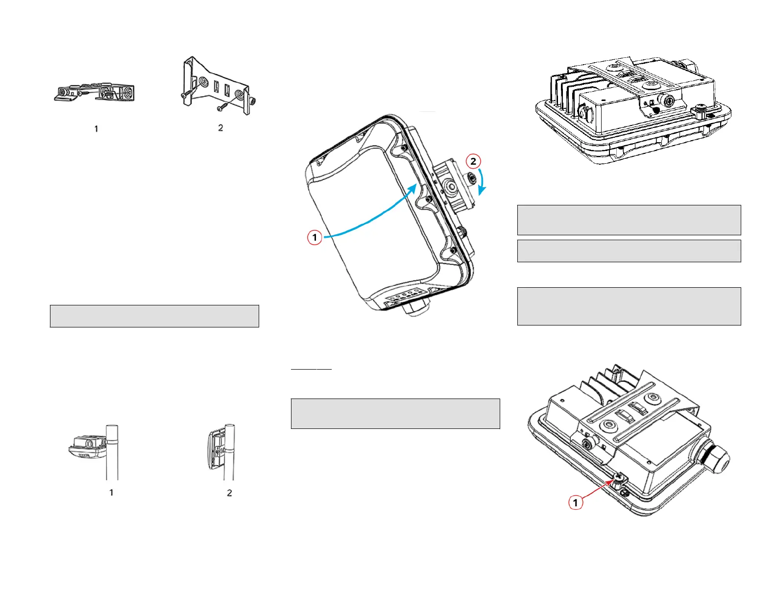
Mounng the AP
1. Snap the AP back onto the mounng bracket, as shown in Figure 11,
and use a medium at-blade or No. 2 Phillips screwdriver to ghten
the capve screw to 1.1 N.m or 10 in-lbs to secure the bracket to the
AP, as shown in Figure 11.
FIGURE 11 Aaching the Mounng Bracket to the AP
1. Snap the AP to the
mounng bracket
2. Tighten the capve
screw
2. Oponal Step: If you also need to lock the mounng bracket to the
AP, then use an appropriately sized screwdriver to screw the
customer-supplied locking stainless steel 6-mm M3 panhead security
screw through the mounng bracket and into the AP chassis.
CAUTION! Make sure that the customer-supplied locking stainless
steel M3 panhead security screw is no longer than 6 mm. If the
security screw is longer than 6 mm, it can damage the AP chassis.
FIGURE 12 Locking the Mounng Bracket to the AP
Earth Grounding the AP
CAUTION! Make sure that earth grounding is available and that it meets
local and naonal electrical codes. For addional lightning protecon,
use lightning rods and lightning arrestors.
NOTE: The color coding of ground wires varies by region. Before
compleng this step, check your local wiring standards for guidance.
Using the factory-supplied ground wire and ground screw and washer set,
connect a good earth ground to the AP chassis ground point.
CAUTION! The T350c AP includes one 9-mm stainless steel M6x1 earth
ground screw with split lock and at washers. Make sure that any
replacement screw is no longer than 9 mm. If a screw is longer than 9
mm, it can damage the AP chassis.
FIGURE 13 Connecng a Good Earth Ground to the AP
1. Earth ground screw
Copyright
©
2021 CommScope, Inc. All rights reserved. Page 3 of 4
Published September 2021, Part Number 800-72904-001 Rev A
 Loading...


