www.commscope.com
User Guide 860633028
June 2018
Page 4 of 30
© 2018 CommScope, Inc. All Rights Reserved
The imVision
®
System
The imVision system is comprised of three main components:
• iPatch Panels, either iPatch copper panels or iPatch fiber shelves
• imVision Controller X (with touchscreen display)
• imVision System Manager software
Multiple imVision Controller X’s are typically connected in a chain to form a patching zone. The first imVision Controller X in
the patching zone must be configured as a Network Manager for the zone and connected to the customer network. A
patching zone may also include imVision Controllers, but such zones have limited functionality. The imVision Controller X
does not support patching zones that contain an iPatch Panel Manager or iPatch Rack Manager Plus.
iPatch
®
Panels
An iPatch Panel monitors connections by sensing the insertion of the patch cord plugs. When a patch cord is added to the
network, the system records the connection in a database. This record lets you trace the connection by pressing the button
near one of the ports containing the patch cord. The LEDs above the connected ports turn on to show where both ends of
the patch cord are located.
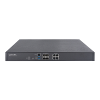
imVision
®
Controller X
The imVision Controller X maintains a database of the patch connections at the rack. It responds to button presses and
sensor changes at the iPatch panels. By monitoring button presses and sensor changes at the panels, the imVision Controller
X logically infers when patch connections are added, moved or deleted and updates the database accordingly.
In most configurations, multiple imVision Controller X units are grouped and connected into
patching zones. Each patching
zone requires a LAN connection in order to communicate with
the System Manager server.
Each imVision Controller X has a touchscreen display that lets you interact with the imVision system in an intuitive way. With
this interface, making and managing connections in the data center has never been simpler.
This powerful display:
• relays guided patch jobs to the technician from the imVision System Manager software
• alerts technicians about equipment issues
• shows detailed port and device information
• prompts technicians on connections that require confirmation
• displays information about the ends of a connection as well as the entire connectivity trace between those end-points
imVision
®
System Manager Software
Using the imVision System Manager Software, the physical infrastructure team can view and manage the patch connections
for the entire network from a workstation. The software documents the physical layer network between faceplates,
consolidation points, panels and network equipment. Through the software, the administrator can schedule work orders for
network changes. Work order steps involving patching are relayed to imVision Controller X’s as patching jobs.
imVision Controller X’s and imVision System Manager work together to track the fulfillment of jobs, display end-to-end circuit
traces, document patching connections and changes, and inform users about system errors or alarms.
 Loading...