G:\Masters\Installation Sheets\Master & Premier\MR40-80P Installation Sheet.doc
Page 8 of 17
8. Electrical Connections
Prior to pump installation ensure that there is at least a two-metre tail on both the incoming
underground mains supply cable and comms cable (if comms enabled). These cables are
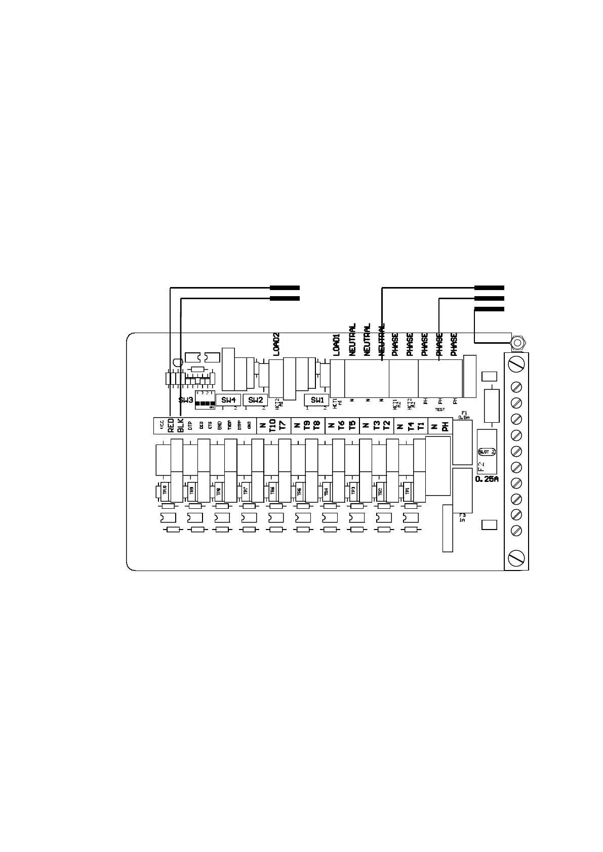
terminated at the C4000 power supply, which is housed in the flameproof enclosure located in
the bottom of the pump, behind the door.
Mains power wiring should be rated for a maximum current draw of 10 A rms at 220-240 V ac.
The incoming cables are terminated as shown in the following picture.
Refer to AS/NZS 60079.14 for appropriate cabling.
Note: All cables entering the power supply must be glanded with approved 20mm flameproof
glands.
Note: Comms cable is not intrinsically safe.
Note: Pump comm’s connect to pump controller such as DCA, Communicator Controller etc.
(option).