11
occur when the discharge temperature
reaches the pre-set maximum discharge
air temperature setting.
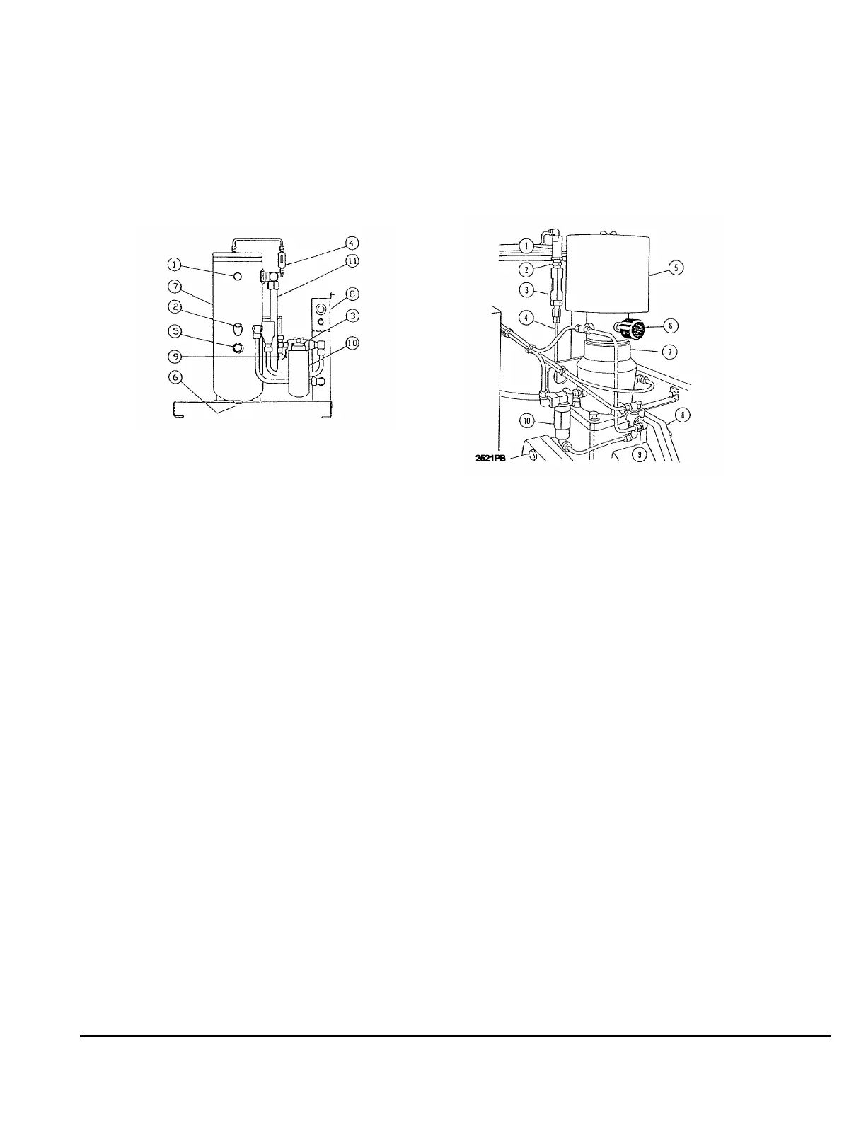
FIGURE 5
1. Restriction indicator (separator)
2. Oil Filler
3. Restriction Indicator (Oil Filter)
4. Separator Drain Line
5. Oil Level Sight Gage
6. Drain Valve
7. Air Receiver/Oil Reservoir
8. Oil Cooler/Aftercooler
9. Oil Sample Valve
10. Oil Filter
11. Discharge Tube
COMPONENT FUNCTION
Piping and wiring diagrams have been
provided to assist in locating components on
the unit and determining component function.
The following explanation of component
function will assist in determining if the
compressor is operating properly.
INTAKE VALVE
The intake valve is located on top of the air
end. The primary purpose of the intake valve
is to control air flow to the air end. The
secondary purpose of the intake valve is to
check reverse air/oil flow when the unit is
shut down.
AIR RECEIVER/OIL RESERVOIR
The air receiver/oil reservoir provides an oil
sump, primary oil separation and a mounting
location for the separator element. The
separator element is mounted at the top of
the air receiver/oil reservoir and held in place
by the receiver/reservoir cover.
FIGURE 6
1. Drain Line Filter
2. Check Valve
3. Sight Gage
4. Separator Drain Line
5. Air Cleaner
6. Restriction Indicator
7. Intake Valve
8. Air End
9. Control Bleed Orifice
10. Return Air Bleed Back Valve
Other components which are mounted on the
receiver/reservoir are the minimum pressure
check valve, with piping, pressure relief valve,
and blow down valve.
MINIMUM PRESSURE/CHECK VALVE
The minimum pressure/check valve is located
on the air receiver/oil reservoir cover at the
separator out port.
The purpose of this valve is to maintain
minimum air pressure in the air receiver/oil
reservoir.
The valve consists of a spring loaded piston
which opens when air pressure reaches
approximately 65 psi and maintains a