31
CONTROL PRESSURE REGULATOR
VALVE SERVICE (Figure 11)
The control pressure regulator valve is
furnished tighter as a complete unit, or may
be serviced with a diaphragm assembly and
valve seat.
Installation of the diaphragm and seat may be
accomplished as follows:
1. Remove the control pressure regulator
from the unit. Mark all tubing
disconnected to aid in correct
reassembly.
2. Loosen the adjusting screw locknut and
turn the screw counterclockwise to
release spring pressure on the
diaphragm.
3. Support the hexagon body in a bench
vise or other suitable fixture. With a
wrench unthread the bonnet from the
body and remove the bonnet.
4. Remove the spring guide and spring
from the body.
5. Remove the diaphragm assembly from
the body and discard.
6. Remove the valve seat from the valve
body. Discard the valve seat.
7. Clean the remaining parts thoroughly.
8. Lubricate the new valve seat with
silicone grease. (Suggest Dow Corning
55M). Install the new valve set in the
valve body, centered over the hole, with
the small chamfer on the outside
diameter down.
9. Install the new diaphragm in the body.
Reinstall the spring and spring guide in
the body.
10. Install the bonnet in the body and tighten
securely.
The control pressure regulator valve may now
be mounted on the unit and adjusted
according to instructions in Section VI of this
manual.
INTAKE VALVE SERVICE
The intake valve may be obtained as a
complete assembly, if required. Service parts
are available, however, to repair the intake
valve is desired.
Do not attempt to disassemble or reassemble
an intake valve while it is mounted on the air
end. Loose or broken parts could accidentally
drop into the air end causing further difficulty.
1. Disconnect the bypass line from the
base of the air cleaner assembly and
thread the air cleaner assembly out of
the intake valve.
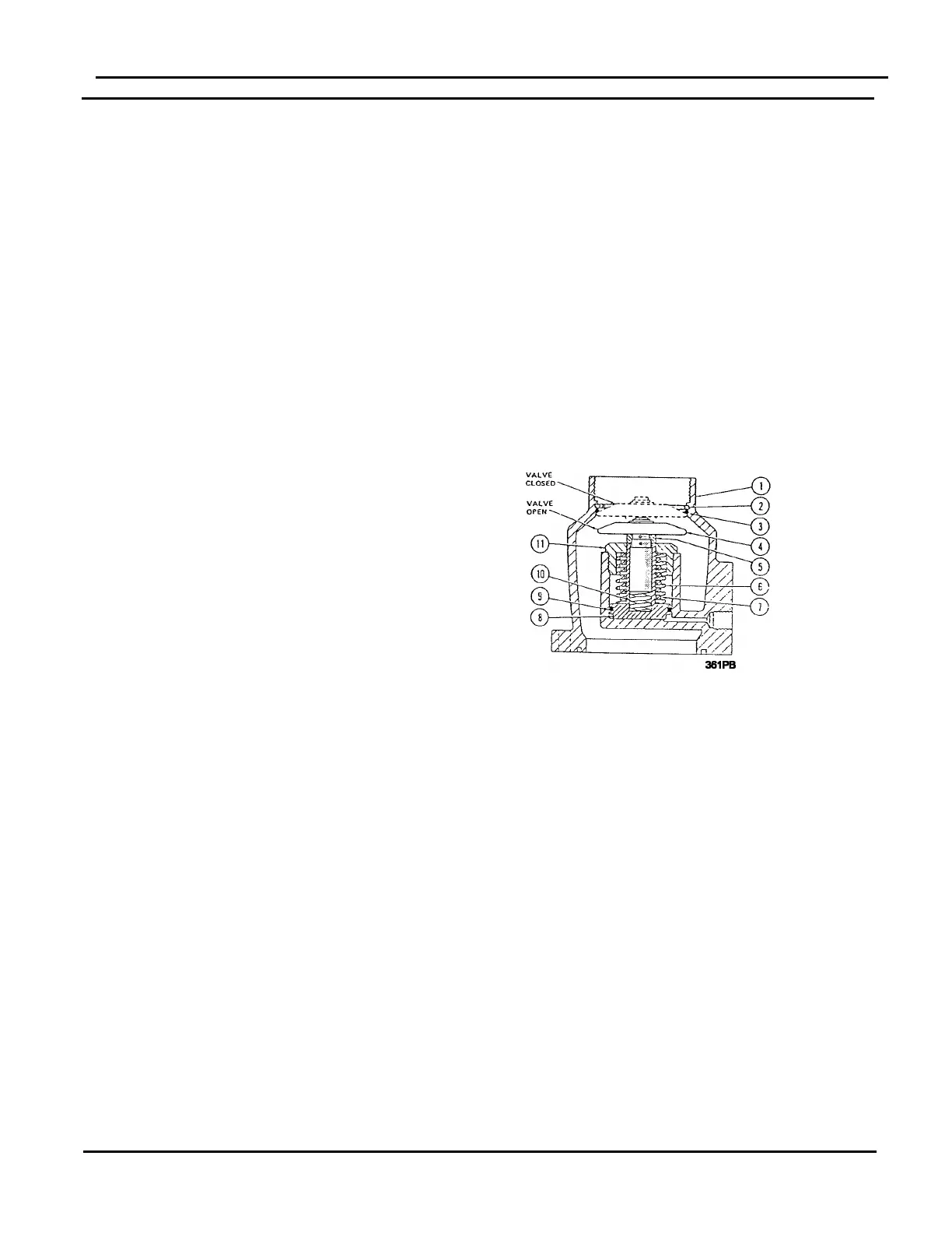
FIGURE 12 - INTAKE VALVE
1. Valve Body
2. Retainer Ring
3. Seal
4. Valve Plate
5. Spacer
6. Spring
7. Spring
8. Piston
9 Seal
10. Spring
11. Cap
2. Disconnect all control air lines (tubes)
from the intake valve. CAREFULLY
MARK THESE LINES TO AID IN
CORRECT REASSEMBLY.
3. Remove the intake valve to air end
attaching capscrews and remove the
intake valve and gasket from the air end.
Discard the gasket.
NOTICE
SECTION VII
SERVICE PROCEDURES - COMPONENTS