34
To install a new separator element, reverse
the above removal sequence. Make certain
the flange and cover surfaces are clean.
Make certain the element flange gaskets
have a grounding staple. Torque the separator
to flange capscrews evenly and securely to
44 ft. Lbs. Make certain, also, that the
separator drain tube touches the bottom of
the element. (Make a new tube, if
necessary).
For information concerning the conditions
which indicate a separator element is
defective refer to the service diagnosis chart,
Section VII.
DANGER
RECEIVER/RESERVOIR COVER
RETAINING STUDS AND NUTS ARE
SPECIAL. DO NOT SUBSTITUTE
COMMON BOLTS OR NUTS IN PLACE OF
THESE SPECIAL STUDS AND NUTS.
AIR END
The air end for these units is serviced only as
a complete assembly using a new or factory
rebuilt air end.
Parts available for field service include the
input shaft rotary oil seal and the fan drive
shaft rotary seal.
Rebuild kits are available for air ends
exceeding the warranty period.
AIR END INPUT SHAFT OIL SEAL
REPLACEMENT (Figure 14)
To replace a rotary seal, proceed as follows:
1. Loosen rocker base spring retainer and
rotate motor toward the compressor to
relieve drive belt tension.
2. Remove the compressor input shaft
drive pulley. Remove belt guard and
disconnect oil lines.
3. Remove the seal retainer (front cover) to
front retainer attaching capscrews and
remove the cover with outer seal.
Discard outer seal.
4. Remove the oil seal assembly, including
the spring and spring guide, from the
input shaft.
5. Remove the oil seal face insert, with o-
ring seal, from the seal retainer. Discard
the face insert, with o-ring seal.
6. Thoroughly clean all remaining parts.
Make certain all gasket material is
removed from the seal cover and front
retainer mating surfaces.
7. Lubricate the new seal face insert with
clean compressor oil and install the
insert in the seal retainer.
8. Lubricate the rotary seal assembly with
clean compressor oil, including the
carbon ring, and install the seal spring
guide, spring, and seal assembly on the
input shaft.
CAUTION
BE CAREFUL NOT TO SCRATCH THE
SEAL FACE INSERT OR SCRATCH OR
BREAK THE CARBON RING OR THE SEAL
ASSEMBLY. WIPE THE LAPPED
(MATING) SURFACES OF THE SEAL
INSERT AND CARBON RING WITH A
CLEAN LINT FREE CLOTH BEFORE
INSTALLING THE SEAL RETAINER.
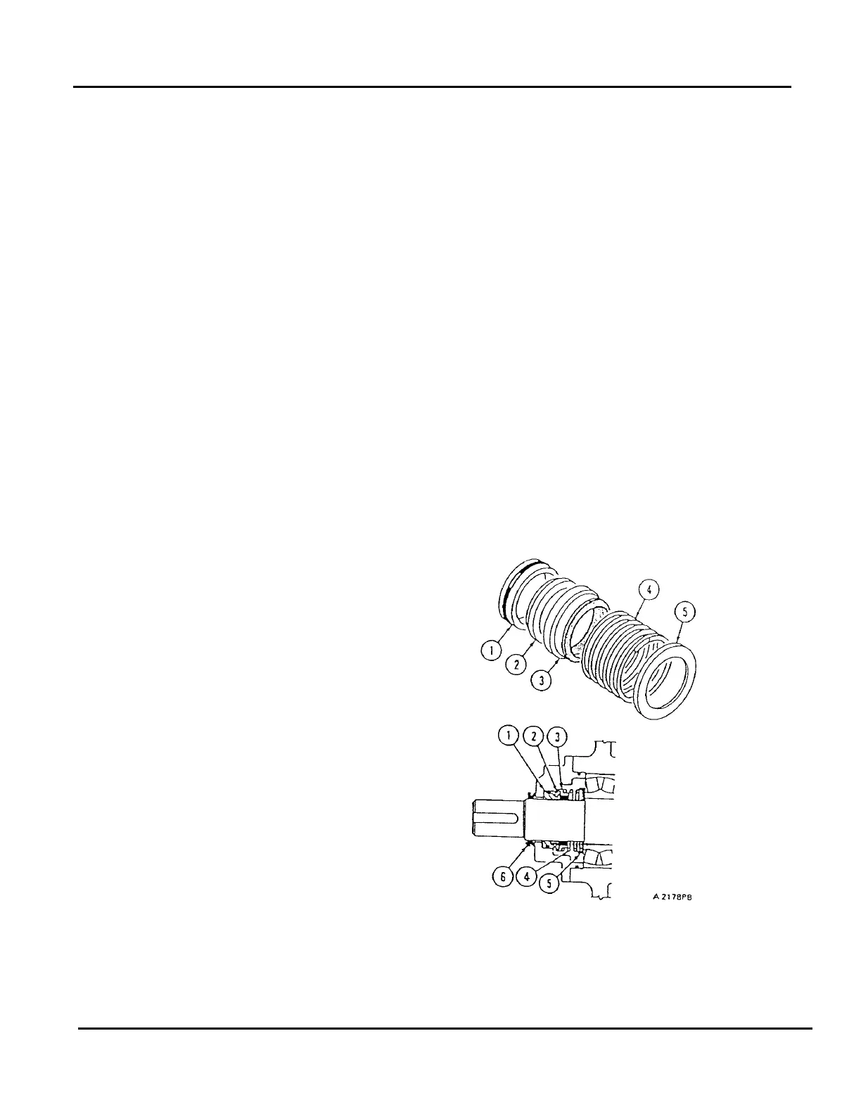
FIGURE 14
AIR END INPUT & FAN SHAFT OIL SEAL
1. Seal Face Insert
2. Carbon Ring