Home
CompAir
Air Compressor
L07
Page 63 (Layout Plan Airstation L07 FS-L11 FS and L07 RS FS-L11 RS FS)
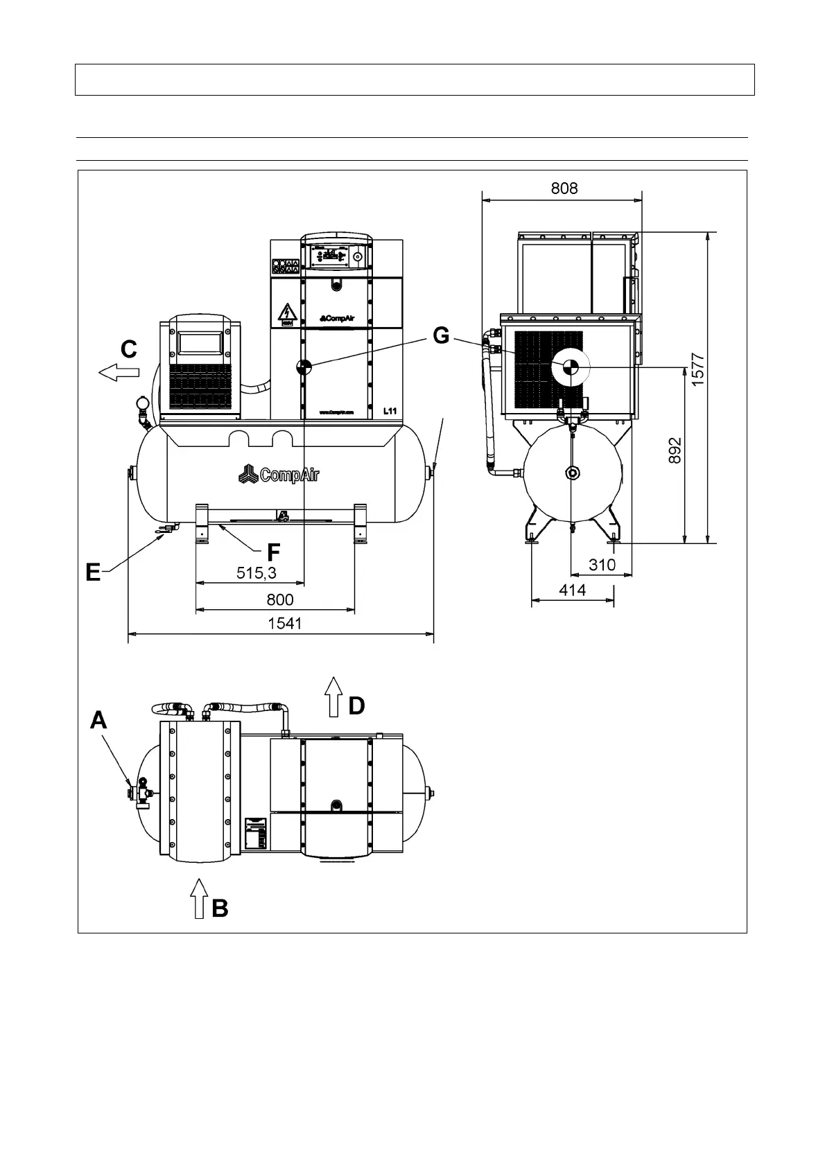
CompAir L07 - Layout Plan Airstation L07 FS-L11 FS and L07 RS FS-L11 RS FS
68 pages
Manual
Save Page as PDF
To Next Page
To Next Page
To Previous Page
To Previous Page
Loading...
11. Annex
61
11.9
Lay
out
pl
a
n Air
St
ati
on L
07F
S-
L11
FS
a
nd L
07
RS
F
S-L1
1RS
FS
PLUG
2”
Fig. 25
(all dimen
sion
s in m
m)
A = Comp
ress
ed air
con
nec
tion G 3/4“
B = Coo
ling ai
r inlet drye
r
C = Coo
ling-air o
utlet d
ryer
D = Coo
ling-air o
utlet comp
resso
r
E = Con
den
sate
drain G 3/8“
F = Fork
lift truck
guida
nc
e
G = Cen
ter of grav
ity
62
64
Table of Contents
Main Page
1 Foreword
5
Notes on the Compressor
5
Intended Use
5
Maintenance
5
Notes
5
2 Table of Contents
7
3 Safety Regulations
9
Identification of Safety Guidelines
9
General Safety Instructions
9
Changes and Modifications to the Machine
10
Installation and Normal Operation
10
Special Work/Maintenance
12
Warning of Special Dangers
14
Storage of Compressors
15
Symbols and Explanations
16
4 Design and Functioning
20
Design of the Unit
20
Design of the Unit - L07-L11 (RS)
20
Design of the Unit - Airstation L07FS-L11FS (RS)
21
Schematic Diagram
22
Oil Circuit
23
Air Circuit
23
System Control
23
System Control L07-L11 / L07FS-L11FS
23
System Control L07RS-L11RS and Airstation L07RS FS-L11RS FS
24
Hood (Opening/Closing)
25
5 Transport and Installation
26
Transport
26
Installation
27
6 Preparations for Commissioning
28
Cooling Air Volume/Minimum Cross
28
Compressed Air Connection
29
Electrical Connection
30
Electrical Connection (EUROPE-Version Only)
30
Electrical Connection (USA/CANADA-Version Only)
32
Electric Motor Fasteners for Secure Transportation
33
Oil Level Check
34
Sound Pressure Level
34
7 Commissioning
35
First Commissioning
35
Routine Commissioning
36
Commissioning after Malfunction
36
8 Control System
37
General
37
Keys
37
Status Indicator (Display / Light Signals)
37
Displaying / Changing Values
38
Selecting Values
38
Changing Values
38
Default Settings
38
Selecting Language
38
Setting Network Pressure (Apart from L07RS-L11RS)
38
Setting Line Pressure (Only L07RS-L11RS)
39
Setting Time/Date (Timer)
39
Starting the Unit
39
Switching off the Unit
39
Emergency off Button
39
Acknowledging Warning / Fault Messages
40
Warning Messages
40
Fault Messages
40
Menu Structure (Apart from L07RS-L11RS) (Values Are Examples)
41
Menu Structure (Only L07RS-L11RS) (Values Are Examples)
42
9 Service and Maintenance
43
Maintenance Recommendations
43
Maintenance Electric Motor
43
Maintenance and Inspection Schedule
43
Oil Change
46
Change of Oil Filter Cartridge
47
Change of the Fine Separator Cartridge
48
Change of Air Intake Filter
48
Safety Valve
49
Changing V-Belts/Automatic Tensioning System
50
Connecting Terminals in the Switch Cabinet/Control Transformer Setting
50
Fittings
50
General Maintenance and Cleaning
51
Clean / Change Cooling Air Filter Mat
51
Inspection Intervals for Pressure Vessels and Electrical Installations
52
Maintenance Information and Lubricant Recommendations for Stationary Compressors
52
10 Trouble-Shooting
53
11 Annex
55
Technical Data EUROPE Version L07-L11 50 Hz
55
Technical Data EUROPE Version L07-L11 60 Hz
56
Technical Data EUROPE Version L07RS
57
Technical Data EUROPE Version L11RS
58
Technical Data Usa/Canada Version L07-L11 60 Hz
59
Technical Data Usa/Canada Version L07RS
60
Technical Data Usa/Canada Version L11RS
61
Layout Plan L07-L11 and L07RS-L11RS
62
Layout Plan Airstation L07FS-L11FS and L07RS FS-L11RS FS
63
Declaration of Conformity
64
Other manuals for CompAir L07
User Manual
56 pages
Related product manuals
CompAir L07RS
68 pages
CompAir L90
72 pages
CompAir L37
72 pages
CompAir L22
72 pages
CompAir L15
72 pages
CompAir L18
72 pages
CompAir L11
68 pages
CompAir L80
72 pages
CompAir L160
72 pages
CompAir L250
72 pages
CompAir L29RS
72 pages
CompAir L45RS
72 pages