5–18 Maintenance and Service Guide
Removal and Replacement Procedures
5.9 Heat Sink
1. Prepare the notebook for disassembly (Section 5.3).
2. Remove the LED switch cover (Section 5.7).
3. Remove the keyboard (Section 5.8).
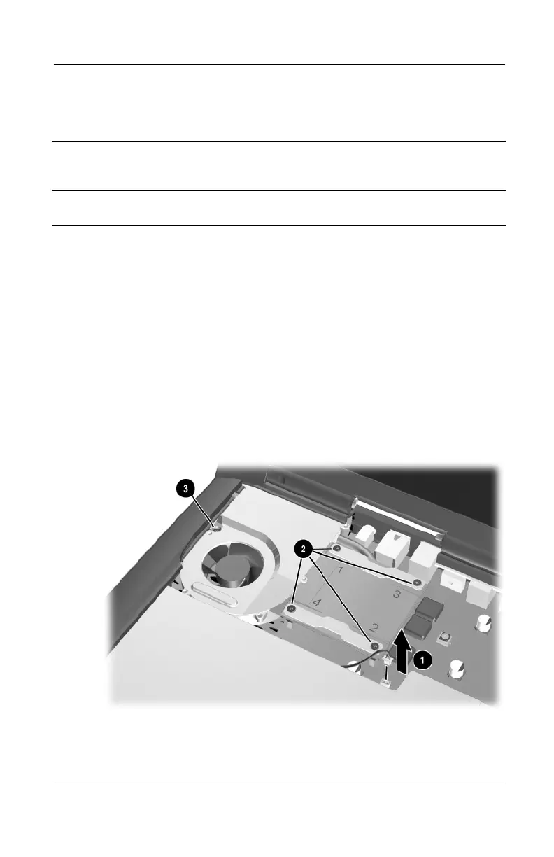
4. Disconnect the fan cable 1 from the system board
(Figure 5-15).
5. Loosen the four PM2.0 × 20.0 shoulder screws 2 that secure
the heat sink to the processor mounting bracket.
6. Loosen the PM2.0 × 16.0 shoulder screw 3 that secures the
heat sink to the base enclosure.
Figure 5-15. Disconnecting the Fan Cable and Loosening the
Heat Sink Screws
Heat Sink
Spare Part Number Information
Heat sink 310647-001
307503-003.book Page 18 Friday, April 4, 2003 3:37 PM
 Loading...