EasyManua.ls Logo

Comparc DELTA MIG 455 - User Manual

Comparc DELTA MIG 455
24 pages
Print Icon
To Next Page IconTo Next Page
Loading...
DELTA MIG 455
ARC WELDING POWER SOURCE
PM1327 REV. 0
E: 21-01-2021
PROCESSES
DESCRIPTION
CONSTANT VOLTAGE OUTPUT (CV).
MIG (GMAW).
DIRECT CURRENT OUTPUT (DC).
THREE PHASES.
3
DC
CV
Phase
OWNES MANUAL
302-573
T M
OWNER´S MANUAL
GIVE THIS MANUALTO THE OPERATOR
VISIT OUR WEBSITE AT: www.comparcwelders.ca
Question and Answer IconNeed help?

Do you have a question about the Comparc DELTA MIG 455 and is the answer not in the manual?

Summary

Safety Signal Words

Specifications

Volt-Ampere Curves

Details minimum and maximum voltage and amperage output capabilities.

Duty Cycle

Defines the percentage of 10 minutes unit can weld at rated load.

Installation

Selecting Location and Moving Power Source

Guidelines for choosing a suitable location and safely moving the welding power source.

Installing Work Clamp

Procedure for correctly installing the work clamp for welding.

Installing MIG Gun Support

Instructions for attaching the support bracket for the MIG gun.

Selecting and Preparing Weld Output Cables

Guidance on choosing appropriate weld cable size and preparing them.

120 V AC Duplex Receptacle

Details on the 120V AC duplex receptacle and its protection.

Shielded Gas Connections

Steps for properly connecting the shielded gas cylinder and regulator.

Remote Receptacles

Information on Remote-14 and Remote ON-OFF receptacles and their connections.

Weld Output Terminals

Description of weld output terminals and proper connection procedures.

Input Power Connections

Instructions for connecting the unit to the appropriate input power supply.

Operation

Controls Location

Identifies the location of all controls on the welding power source.

Power Switch Operation

Details on how to turn the welding power source on and off.

Output Switch Function

Explains the function of the output switch for panel or remote control.

Voltage Control Switch

Describes the voltage control switch for panel or remote voltage adjustment.

Voltage Adjustment Control

How to adjust the arc voltage output using the dedicated control.

Digital Meters

Explanation of the digital voltmeter and ammeter readings.

Safety Equipment

Lists and describes essential safety equipment for welding operations.

Operation Sequence

Step-by-step procedures for GMAW, FCAW, SAW, and CAC-A welding processes.

Maintenance and Troubleshooting

Routine Maintenance Schedule

Schedule and tasks for regular maintenance of the welding equipment.

Overheating Protection

Explanation of the unit's overheating protection system and indicators.

Overload Protection

Details on circuit breakers, fuses, and overload protection mechanisms.

Troubleshooting Guide

Common problems and their remedies for welding output and wire feeding.

Electrical Diagram

Parts List

Main Assembly Parts

List of components for the main assembly of the welding unit.

Rectifier Assembly Parts

List of components specific to the rectifier assembly.

Limited Warranty

3 Years Parts & Labour Warranty

Covers major components like transformer, rectifiier, PC board, etc. for 3 years.

1 Year Parts & Labour Warranty

Covers items like track cutters, positioners, and cooling systems for 1 year.

90 Days Parts & Labour Warranty

Covers items like MIG guns, torches, regulators for 90 days.

Engine Warranty

Details that the engine is warranted separately by the manufacturer.

Warranty Exclusions

Lists consumables and normal wear items not covered by the warranty.

Voiding Warranty Conditions

Conditions under which the limited warranty becomes void.

Making a Warranty Claim

Instructions on how to submit a warranty claim and required information.

Service Center Information

Overview

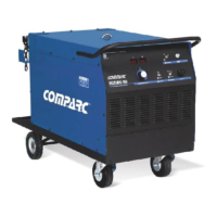
The COMPARC DELTA MIG 455 is an ARC WELDING POWER SOURCE designed for various welding processes, primarily MIG (GMAW), but also supporting FCAW, SAW, and CAC-A. This robust machine provides a constant voltage (CV) output and operates on direct current (DC), making it suitable for a wide range of industrial and professional welding applications. It is designed to operate on a three-phase power supply.

Function Description

The DELTA MIG 455 serves as the core power source for arc welding, providing the necessary electrical output to melt and join metals. Its primary function is to deliver a stable and controllable arc for consistent weld quality.

For MIG (GMAW) welding, the machine provides a constant voltage output, which is ideal for feeding a continuous wire electrode into the weld puddle. This process is known for its speed and efficiency, making it suitable for various materials and thicknesses. The machine supports both solid wire and flux-cored wire applications.

The DELTA MIG 455 also supports FCAW (Flux-Cored Arc Welding), which uses a continuously fed tubular electrode containing flux. This process is versatile and often preferred for outdoor welding or on materials with some surface contamination, as the flux provides shielding.

SAW (Submerged Arc Welding) is another process supported by this power source. SAW involves a continuously fed wire electrode and a granular flux that completely covers the arc, protecting it from atmospheric contamination. This results in high-quality welds with deep penetration, often used for heavy fabrication.

Finally, the machine can be used for CAC-A (Carbon Arc Cutting and Gouging), a process that uses a carbon electrode to melt metal, which is then blown away by a jet of compressed air. This is effective for cutting, gouging, or removing welds.

The machine features a user-friendly control panel with a "POWER" switch for turning the unit on and off, an "OUTPUT" switch to energize the weld output terminals (either via the front panel or a remote device), and a "V CONTROL" switch to select between panel or remote voltage control. A "VOLTAGE ADJUSTMENT" control allows the operator to precisely increase or decrease the arc voltage. Digital meters display both the preset and actual output voltage and amperage, providing real-time feedback during welding. These meters retain the arc values for a few seconds after the arc is extinguished, aiding in post-weld analysis.

Input power connections are flexible, allowing the machine to operate on different three-phase voltages (230V, 460V, 575V) by adjusting internal jumper links. This adaptability ensures compatibility with various industrial power supplies. The machine also includes a 120V a.c. duplex receptacle for auxiliary power, protected by a circuit breaker. Remote 14 and ON-OFF receptacles provide connectivity for remote control devices, enhancing operational convenience and safety.

Usage Features

The DELTA MIG 455 is designed with several features to optimize its use and ensure operator safety.

Installation and Setup:

  • Location: The machine requires at least 10 inches (254 mm) of open space on its right and left sides for adequate airflow, crucial for cooling.
  • Mobility: A lifting eye is provided for safely moving the unit with appropriate lifting equipment.
  • Work Clamp: The work clamp is installed by connecting the work cable from the unit to a contact piece, secured with a screw and washer. Proper grounding of the workpiece is essential for safety and effective welding.
  • MIG Gun Support: A dedicated support for the MIG gun can be easily installed on the machine's cover and side deck using screws, providing a convenient and secure place for the gun when not in use.
  • Weld Output Cables: The selection of weld cable size is critical and depends on the total cable length, maximum welding current, and duty cycle. The manual provides a detailed table to guide operators in choosing the correct copper cable size to minimize voltage drop and ensure efficient power delivery.
  • Shielded Gas Connections: For processes requiring shielding gas, the machine connects to gas cylinders via a regulator/flowmeter. Proper cylinder handling, including securing them to prevent tipping and opening valves carefully, is emphasized for safety.
  • Input Power: Jumper links inside the machine allow for configuration to different input voltages (230V, 460V, 575V three-phase). This must be correctly set to match the available power supply, and appropriate cable sizes and fuses/circuit breakers are recommended based on the input voltage and rated current.

Operation:

  • Controls: The front panel controls are clearly labeled for intuitive operation. The "POWER" switch turns the unit on/off. The "OUTPUT" switch enables either local (panel) or remote control of the weld output. The "V CONTROL" switch selects between panel or remote voltage adjustment. The "VOLTAGE ADJUSTMENT" knob fine-tunes the arc voltage.
  • Digital Meters: The digital voltmeter and ammeter display preset voltage when the contactor is off and actual output voltage and amperage when the contactor is on. This allows operators to monitor welding parameters in real-time.
  • Safety Equipment: Operators are strongly advised to wear appropriate personal protective equipment (PPE), including dry insulating gloves, safety glasses with side shields, a welding helmet with the correct filter shade, and approved ear protection (plugs or muffs) if noise levels are high.

Operation Sequences:

The manual outlines specific operation sequences for each welding process:

  • GMAW (Solid Wire): Install and connect equipment, prepare wire feeder, put on safety equipment, turn on wire feeder and power source, open gas valve, adjust controls, and begin welding.
  • FCAW (Flux Cored Arc Welding): Similar to GMAW, but with specific steps for preparing the flux system.
  • SAW (Submerged Arc Welding): Involves installing and connecting equipment, preparing the wire feeder and flux system, putting on safety equipment, and then beginning welding.
  • CAC-A (Air Cutting and Gouging): Requires connecting a compressed air system, selecting the carbon electrode, and then starting cutting or gouging.

Maintenance Features

Regular maintenance is crucial for the longevity and safe operation of the DELTA MIG 455. The manual provides a clear schedule for routine maintenance tasks.

Routine Maintenance Schedule:

  • Every Month (or more frequently with heavy use):
    • Check all labels for readability and replace any that are worn or damaged.
    • Inspect and repair any damaged insulation on cables or replace the holder or work cable.
    • Clean internal parts of the machine.
    • Clean and tighten connections at the holder cable and work clamp.
  • Every 3 Months:
    • Replace unreadable labels.
    • Tape or replace cracked cables.
    • Clean and tighten weld terminals.
    • Replace cracked parts.
  • Every 6 Months:
    • Blow out or vacuum the inside of the machine to remove dust and debris. This should be done monthly during heavy service.

Overload Protection and Troubleshooting:

  • Overheating Protection: The unit is designed with a cooling system to maintain safe operating temperatures. If the temperature rises to unsafe levels, the output will be interrupted, and the digital meters will display "ESP ErE." The cooling system will continue to operate until the machine cools down to a safe operating temperature, at which point the output will restart, and the "ESP ErE" message will disappear. In cases of severe overheating or cooling system failure, the machine will shut down and disconnect from the power line.
  • Overload Protection:
    • Circuit Breaker CB1 (10 AMP): Protects the 120V a.c. circuit from overload. Pressing the button resets the breaker.
    • Circuit Breaker CB2 (10 AMP): Protects the 24V a.c. circuit from overload. Pressing the button resets the breaker.
    • Fuse F1 (5 AMP): Protects the control transformer from overload. If F1 is open, the fan motor and output unit will stop. If F1 is open, it must be replaced.
    • Before any inspection or restart, the unit must be disconnected from power, and the access door must be closed and secured.
  • Troubleshooting Guide: The manual includes a troubleshooting table for common issues:
    • No weld output, unit completely inoperative: Check if the line disconnect device is ON, inspect and replace fuses/reset circuit breakers, verify proper input power connections, and ensure the power switch is ON.
    • No weld output, wire does not feed but motor fan runs: Consult a dealer or Service Center to review connections and the electronic board. Ensure the plug trigger connector is in the receptacle and the work clamp is on the workpiece.
    • Low weld output current: Verify that jumper links are correctly positioned for the available voltage and adjust the control voltage according to the application.
    • Wire feed but stops during welding process: Check the torch according to its owner's manual and replace damaged parts. Readjust drive roll pressure, inspect and replace the contact tip, remove any obstructions in the wire feeder mechanism, ensure the plug trigger connector is in the receptacle, and consult a dealer or Service Center for issues with the electronic board in the power source or wire feeder.

By adhering to these maintenance guidelines and troubleshooting steps, operators can ensure the reliable and safe performance of their COMPARC DELTA MIG 455 welding power source.

Comparc DELTA MIG 455 Specifications

General IconGeneral
Input Voltage3 x 400 V
Protection ClassIP21S
Wire Diameter0.8-1.6 mm
Weight47 kg
Welding ProcessMIG

Related product manuals