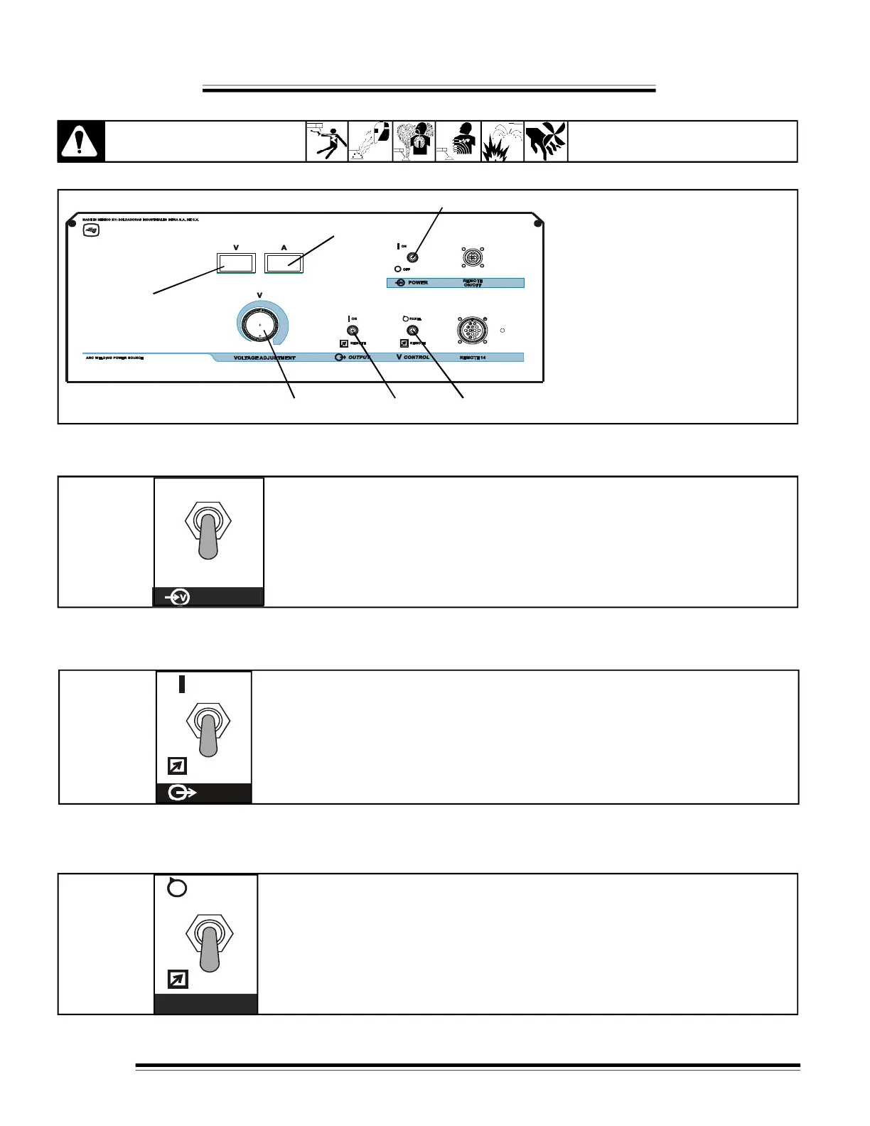
4-1 LOCATION OF CONTROLS IN WELDING POWER SOURCE.
8
CAUTION
SECTION - 4 OPERATION
SEE SAFETY SIGNALS AT THE
BEGINING THIS MANUAL
Figure 4-1 Controls
1- ''POWER'' Switch.
ON - OFF
2- ''V CONTROL'' Switch.
PANEL - REMOTE.
3- ''OUTPUT'' Switch.
ON-REMOTE.
4- ''VOLTAGE ADJUSTMENT'' Control.
Turn clockwise to increase voltage.
5- Digital voltmeter.
6- Digital ammeter.
Figure 4-2. " POWER ''
* POWER switch
Turn on and turn off the power source.
OFF
POWER
ON
REMOTE
* OUTPUT switch
PANEL position for front panel control of output, weld output terminals are
energized.
REMOTE position for remote control of output, needed connect remote device
in Remote - 14 receptacle.
Figure 4-3. ''OUTPUT''
H
E
C
H
O
E
N
M
E
X
I
C
O
1
2
3
5
4
6
4-2 ''POWER'' SWITCH
4-3 ''OUTPUT'' SWITCH
* Voltage CONTROL switch
PANEL position for front voltage control.
REMOTE position for remote voltage control, needed connect
remote device in Remote-14 receptacle.
Figure 4-4. ''V CONTROL''
4-4 ''V CONTROL'' SWITCH
PANEL
REMOTE
V