OUTPUT
(CONTACTOR)
INFORMATION
Socket
REMOTE-14
A
B
I
J
G
K
C
E
D
F
H
24 V a.c. Protected by CB2 (10 Amperes).
Contact closure to "A" completes 24 V a.c. contactor control circuit.
120 V a.c. Protected by CB1(10 Amperes).
Contact closure to "I" completes 120 V a.c. contactor control circuit.
Circuit common for 24 and 120 V a.c. circuits.
Chassis common.
Command reference 10 V d.c.
0 to +10 V d.c. input command signal from remote control.
Remote control circuit common.
Current feedback 0-10 V d.c. 1 Volt per100 weld output Amperes.
Voltage feedback 0-10 V d.c. 1 Volt per 10 weld output Volts
NOTE: Remaining sockets are not used
TABLE 3-2. REMOTE-14 RECEPTACLE INFORMATION.
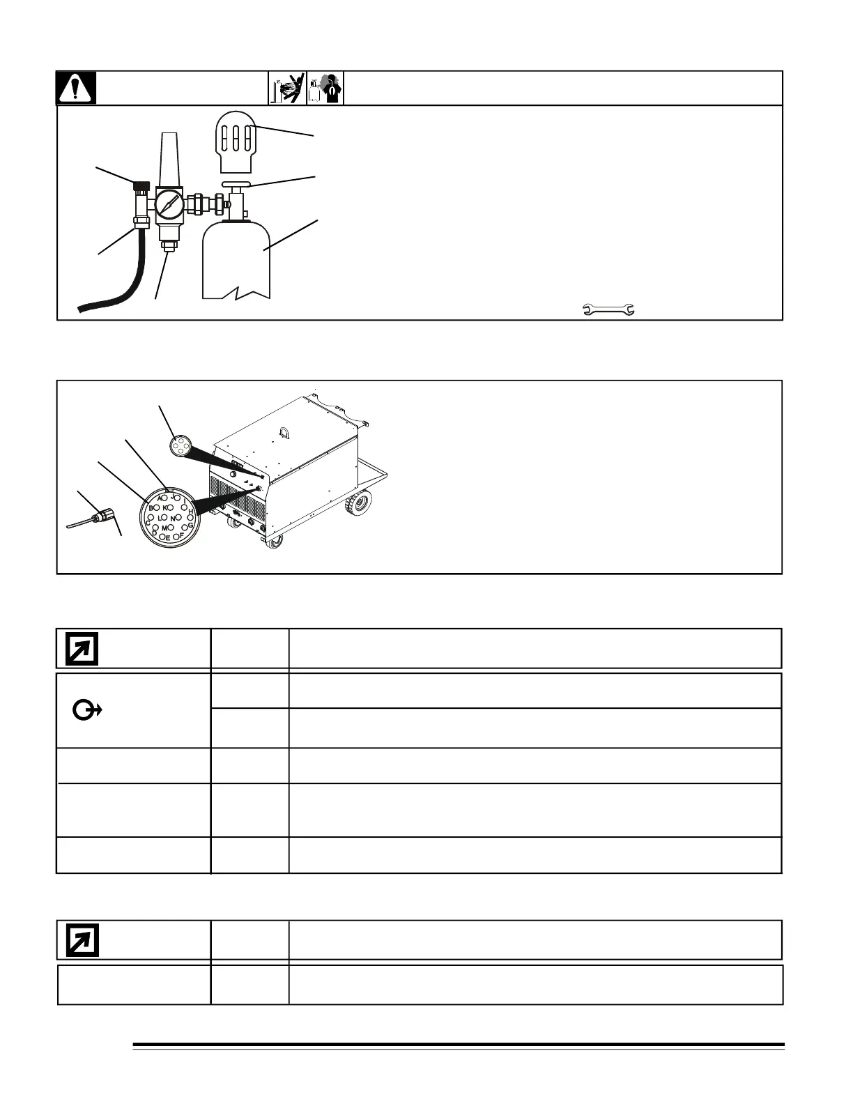
Figure 3-6 Shielded gas connection.
WARNING
SEE SAFETY SIGNALS AT THE BEGINING THIS MANUAL
6
3-6 SHIELDED GAS CONNECTIONS.
Figure 3-7. Remote-14 and Remote ON-OFF
3-7 REMOTE 14 AND REMOTE ON-OFF RECEPTACLES
1- Remote-14 receptacle RC8 (See table 3-2)
2-
Keyway
3- Plug connector 14
4- Collar
5- Remote ON-OFF receptacle (See table 3-3)
To connect this receptacle, align keyway, insert plug and
tighten threated collar.
Turn off power before connecting remote 14 or
remote ON-OFF receptacles
1
2
3
4
5
6
G N D
REMOTE OUTPUT
CONTROL
A / V
INFORMATION
SOCKETS
REMOTE ON-OFF
TABLE 3-3. REMOTE ON-OFF RECEPTACLE INFORMATION.
24V a.c. with 'POWER'' switch in ''OFF'' position.
Contact closure to "2" completes 24 V a.c. remote power circuit.
ON-OFF
RMT
2
3
Be sure gas cylinder is held to running gear, wall, or other stationary support
so cylinder can not fall and break off valve.
1.- CAP.
2.- CYLINDER VALVE.
Remove cap, stand to side of valve, and open valve slightly. Gas flow blows
dust and dirt from valve. Close valve.
3.- CYLINDER.
4.- REGULATOR /FLOWMETER.
5.- GAS HOSE CONNECTION.
6.- FLOW ADJUST.
Typical flow rate is 20 cfh ( Cubic Feet per Hour).
28.5, 15.8mm (1-1/8",5/8")
Tools needed:
NOTE: Remaining sockets are not used
1
3
4
2
3
4
2
1
5
 Loading...