11COMPRAG Screw air compressor A-Series
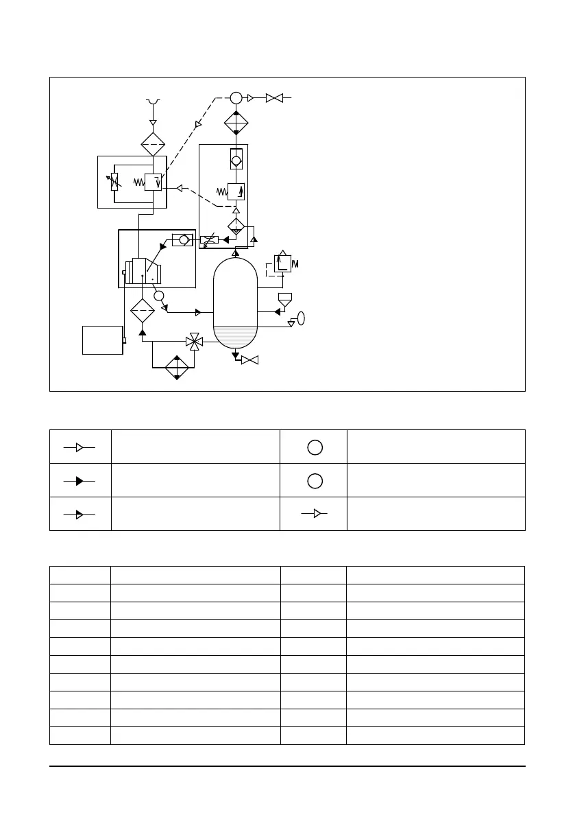
2.3 Function diagram and main components
Air ow
Temperature sensor
Oil ow
Pressure sensor
Air/Oil mix ow
Pneumatic control line
Main components
1 Electric motor 11 Min. Pressure valve
2 Belt drive 12 Non-return valve
3 Air end 13 Heat-exchanger, Air section
4 Air lter 14 Heat-exchanger, Oil section
5 Intake valve 15 Thermostatic valve
6 Air-Oil separation tank 16 Oil lter
7 Safety valve 17 Drain valve
8 Air-Oil separator 18 Oil lling plug
9 Throttle valve 19 Oil level sight glass
10 Non-return valve 20 Air outlet valve
М
Р
Т
16
14
15
17
19
18
6
2
1
3
10
9
4
5
8
7
11
12
13
20
Fig. 2.1 Function diagram A07..-A22..