13COMPRAG Screw air compressor A-Series
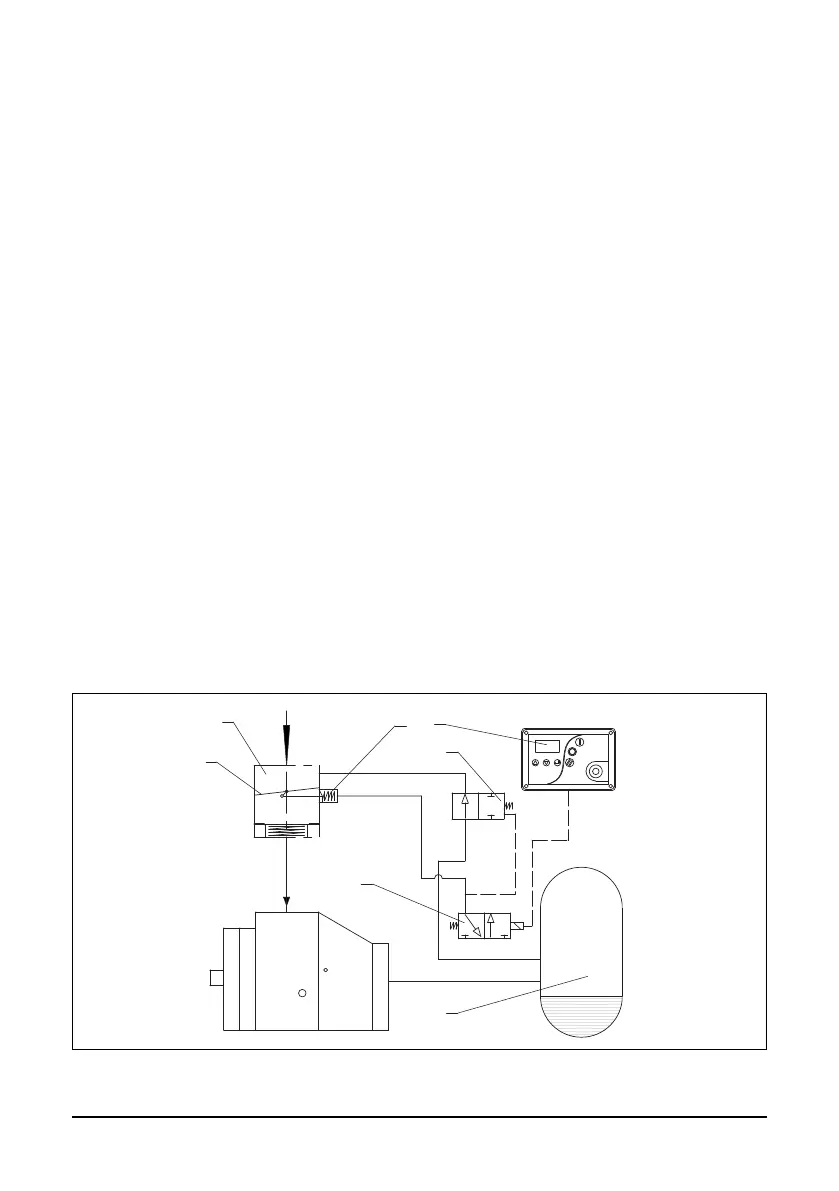
2.4 Functional description (see Fig. 2.1 and Fig. 2.2)
Air ow:
Air drawn through Air lter (4) and open Intake valve (5) into compressor Air-end (3) is compressed.
Compressed air and oil ow into Air-Oil separation tank (6). The air is discharged via Min.
Pressure valve (11) through Heat-exchanger (13) towards the Air Outlet Valve (20).
Oil ow:
Air pressure forces oil from the air-oil separation tank (6) through the heat-exchanger (14)
and the oil lter (16) to the compressor air-end (3) and the lubrication points. In the air-oil
separation tank (6), most of the oil is removed centrifugally; the rest is removed by the
air-oil separator (8).
The oil system is tted with a thermostatic valve (15). When the oil temperature is below
the set-point of the thermostatic valve, the thermostatic valve shuts off the oil supply
from oil heat-exchanger (14). The thermostatic valve starts opening the supply from heat-
exchanger (14) when the oil temperature exceeds the valve’s setting. The setting of the
thermostatic valve depends on the model. See table Technical Data.
Cooling system:
The cooling system comprises a combined air section (13) and an oil section (14) heat-
exchanger. A cooling fan, mounted directly on the motor shaft, generates the cooling air in
order to cool the heat-exchanger.
2.5 Regulating system
Fig. 2.3 Regulating system