3
_______________________________________________________________________________________________
DETAILED WIRING GUIDE
Important Note: Before you make all your wire connections and connect the additional items please review the
Option Programming Tables and the descriptions at the end of this manual.
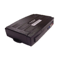
CONNECTOR 1 (CN1)
Pin 1 Red - Constant 12-volt (+) positive power input for the control module. This wire must be connected to a
constant 12-volt (+) positive source. The proper wire will test 12-volt (+) positive with the key in the off
position, while key is in the on position and during crank.
Pin 2 Green/White - This is a dual purpose wire that is selectable thru the trunk/light jumper on the control module.
The jumper position will dictate the output of this wire.
Parking light - Parking light (+) positive output. Connect this wire to the (+) positive parking light wire
generally at the parking light switch or behind the fuse box. The proper wire will test 12-volts (+) positive when
the parking light switch is in the on position.
Trunk release - This wire will test 12-volts (+) positive when the trunk release is triggered.
Pin 3 Red/White - Constant 12-volt (+) positive power input for the starter and accessory on-board relays. This wire
must be connected to a constant 12-volt (+) positive source. The proper wire will test 12-volts (+) positive with
the key in the off position, while the key is in the on position and during crank. This pin also has a red/white
wire that is prewired to a relay. The relay also has a short violet wire on pin 85. This is the input from one of the
negative (-) outputs for Ignition, Accessory or Starter on CN3 There is also a long blue wire on pin 30 that
becomes your 2
nd
Ignition, 2
nd
Accessory, or 2
nd
Starter trigger. This diagram explains the purpose of the relay.
Pin 4 White
- Accessory 12-volts (+) positive output. This wire must be connected to the heater and A/C blower
motor wire. The proper wire will test 0-volts with the key in the off position, 12-volts (+) positive while key is
in the on position, 0-volts while cranking and back to 12-volts (+) positive with the key in the on position
.
Pin 5 Violet
- 250mA (-) negative output when armed and remote started. This wire will provide a (-) negative output
when system is locked and armed and during remote start for anti-grind. (Note: This wire can also be used to
trigger after-market L.E.D. kits and other after-market accessories. Output must be diode isolated when
used to trigger after-market accessories.)
Pin 6 Yellow - Starter 12-volt (+) positive output. This is pre-wired to pin 87a of the starter interrupt relay. This wire
will provide12-volts (+) positive to the vehicle’s starter. The proper wire will test 0-volts with the key in the off
position, 0-volts while the key is in the on position and 12-volts (+) positive during crank. (Note: The vehicle