12-2
Kenwood Transceiver Weather Station Interface
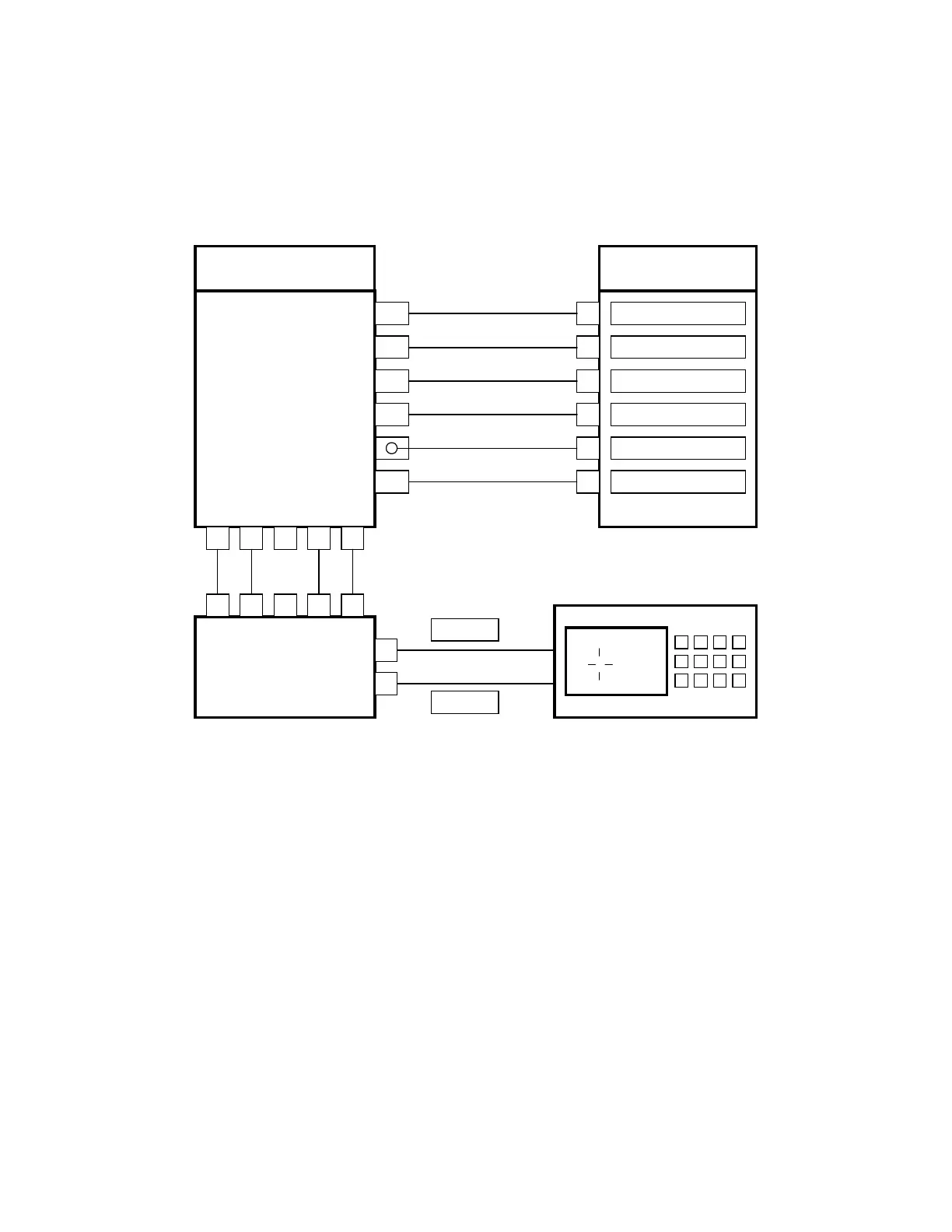
In this configuration the CAT-200B is connected to the microphone jack of the Kenwood TM-421
transceiver. Voltage to power the CAT-200B is derived from the +8VDC output pin #5 of the
microphone jack. The equipment is located at the repeater trustee’s house and tuned to the repeater
output. When the proper DTMF command is received, the CAT-200B will key the transceiver and send
a weather report to the input of the repeater. The CAT-200B will also work in parallel with a Peet
Brothers Weather Station and a packet modem.
KENWOOD
TRANSCEIVER
CAT-200B
J3
J2
MICROPHONE
CONNECTOR
CI-200
1 2 3 4 5
1 2 3 4 5
9
5
76 F
N
E
S
W
1
2
6
7
5
8
TX AUDIO
GROUND
+8VDC
GROUND
RX AUDIO
PTT
23
25
13
10
GREEN
BLACK
J1
J3
J5
Figure 12-2
Transceiver Control Channels
In this mode the CAT-200B has two control zones for a total of sixteen control channels. These channels
are controlled by DTMF commands on the transceiver’s input.
Interrogation of Transceiver Control Status by Radio
Key-up and send the control operator code [100] followed by the zone number and a zero. Un-key and
the voice will read back the channels that are turned on in that zone. Example: "ONE TWO FIVE ON." If
all the channels are turned off, the voice will say: "CLEAR."