24
COMUNELLO ®Copyright 2019 - All rights reserved
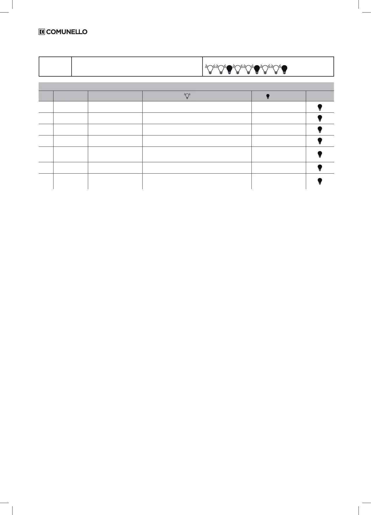
The third menu is the one dened as EXTENDED 2 and to access the programmable functions follow the instructions given in Tab. 4:
EXTENDED
MENU 2
• Press the SELECT button and scroll the LED menu until you
reach the LEV LED;
• Press SET twice to access the EXTENDED menu 2.
The LED of the LEV function FLASHES with this frequency
LIVEL 2 - EXTENDED MENU 2
LED FUNCTION DESCRIPTION LED ON LED OFF DEFAULT
L1 SOFT STOP Setting of gradual slowdown at
the end of the movement
Enabled function Disabled function
L2 SOFT START Setting of gradual slowdown at
the beginning of the movement
Enabled function Disabled function
L3 DS1 IN OPEN Photocell DS1 acts with momen-
tary stop in the opening phase
Enabled function Disabled function
L4 HOLD-TO-RUN Hold-to-run input Enabled function Disabled function
L5 FOLLOW ME The motor automatically closes in
5 sec after passing through DS1
photocell
Enabled function Disabled function
L6 LAMP IN PAUSE Lamp. active during pause time
(if set)
Enabled function Disabled function
L7 "ALWAYS CLOSE" Enables a command in CLO-
SURE when the power supply is
restored
Enabled function Disabled function
TAB.04
Important note: The control unit allows to be programmed if all the safety devices and buttons (N.C. inputs on terminals) grant a contact closed.
6 DETAILED DESCRIPTION OF ALL
FUNCTIONS
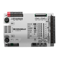
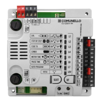
6.1 ELECTRICAL CONNECTIONS
CN1:
L: 230 V line input~ (Phase)
N: 230 V line input~ (Neutral)
MOT1 OPEN: Motor 1 opening output
MOT1 COM: Motor 1 common output.
MOT1 CLOSE: Motor 1 closure output
CN2:
STOP: Emergency stop input (NC)
GND: Common GND input.
LAMP+: Signal light output (24 V~ 4W max)
FOTO+: Photocell power supply (24V~ 5W max)
GND: Common power supply (GND)
FCC: Motor Closing Limit Switch input (NC).
FCA: Motor Opening Limit Switch input (NC).
GND: Common GND input
DS1: Safety device input (NC)
PP: Step-by-Step open-close command button input (NO).
ANT-: Antenna chassis input
ANT+: Antenna hot pin input
TRANSFORMER CONNECTIONS
CN3 Primary:
1: Transformer primary winding input 230 V~.
2: Transformer primary winding input 230 V~.
CN4 Secondary:
1: Output SEC 1 Transformer 12.5V, 0.17A no-load voltages.
2: Output SEC 1 Transformer 12.5V, 0.17A no-load voltages.
3: Output SEC 2 Transformer 24.5V, 0.4A no-load voltages.
4: Output SEC 2 Transformer 24.5V, 0.4A no-load voltages.
6.2 FUNCTIONAL CHARACTERISTICS
6.2.1 AUTOMATIC OPERATION (OPEN/CLOSE):
When either a stored remote or the connected low voltage pushbutton panel is
used to control the gate, operation is as follows:
the rst command opens the gate until motor time elapses or until the gate
reaches its opening limit position; the second command closes the gate; if
another command is transmitted before motor time has elapsed or before one
of the two limiters has been reached, the control unit reverses the movement
direction during both opening and closing.
6.2.2 STEP-BY-STEP OPERATION:
With the enabled function (LED L2 turned ON by factory), when either the
remote or the low voltage control pushbuttons are used to control the gate,
operation is as follows:
the rst command opens the gate until motor time or until the gate reaches
its opening limit position; the second command closes the gate; if another
command is transmitted before motor time has elapsed or before one of the
limit stops has been reached, the control unit stops the movement (if the pause
time was previously programmed, the control unit automatically closes at the
end of the period). Another command causes the gate to start moving again in
the opposite direction.
6.2.3 STEP-BY-STEP WITH CLOSURE:
With the enabled function, when either the remote or the low voltage control
pushbuttons are used to control the gate, operation is as follows:
the rst command opens the gate until motor time or until the gate reaches
its opening limit position; the second command closes the gate; if another
command is transmitted before motor time has elapsed or before one of the
limit stops has been reached,
the control unit always stops the movement both during the opening and closing
phases (even if the pause time has been previously programmed). Another
command causes the gate to start moving again in the opposite direction.
6.2.4 AUTOMATIC CLOSING:
The control unit can be set up to close the gate automatically without sending
any additional commands.
The selection of this type of operation is described in Pause time programming
mode PAUSE TIME.
6.2.5 PEDESTRIAN OPENING:
The control unit allows, using both the radio control and the Ped input button,
the operation of the Motor for a programmable time (equal to or less than the
one stored with the “Motor time”, see section 7.2.2).
6.2.6 EMERGENCY STOP INPUT:
The control unit allows the connection of the emergency stop button (NC).
Intervention of the control unit during any stage of operation causes movement
to immediately stop. An additional movement command will be valid provided
the emergency stop input has been disabled with pre-ashing for 5 seconds.
Note: Input closed by factory; take out the jumper once you connect the button.
 Loading...