34
COMUNELLO ®Copyright 2019 - All rights reserved
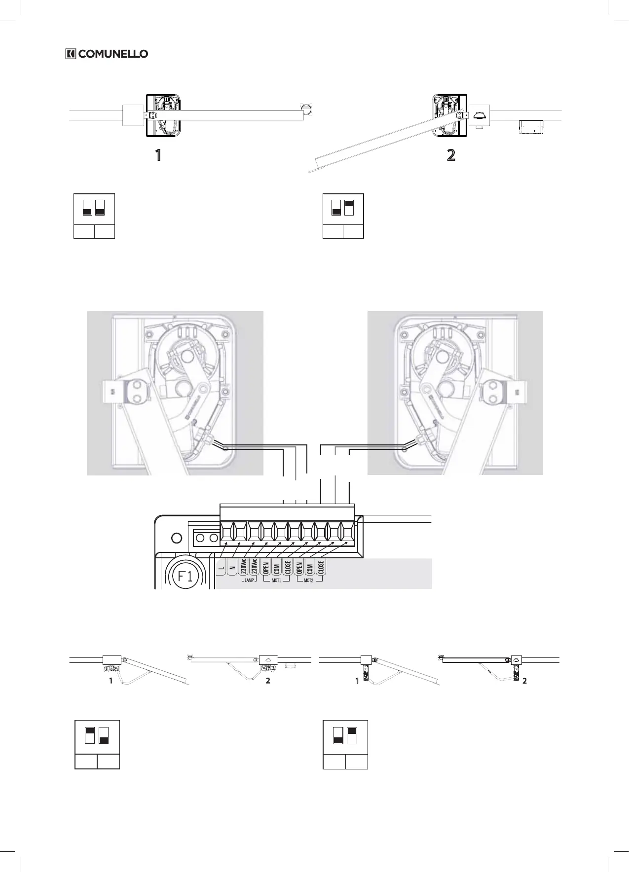
DELAY OF THE MOTOR no.1
1 2
2
MOTOR
DELAY
MOT. 1
1
ON
2
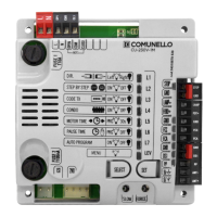
SW1
DIP1 ON = 2 motors congu-
ration
DIP2 ON = Delay of motor no. 1
INV
OFF
INV
MOT. 2
1
ON
2
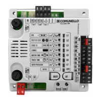
SW2
DIP1 ON = 2 motors congu-
ration
DIP2 OFF = Delay of motor no. 2
Wire connection of the motors (version without encoder) to the control unit:
Conguration - MOTOR NO.1 ON THE LEFT, MOTOR NO.2 ON THE Rights
MOTORE n.1 (LEFT)
NERO in OP1
BLU in CM1
BROWN on CL1-
MOTORE n.2 (Rights)
BLACK with OP2
BLUE on CM2
BROWN on CL2
CN1
L
N
OP1
CM1
CL1
OP2
CM2
CL2
230V
230V
Brown
Brown
Black
Black
Blue
Blue
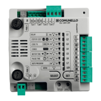
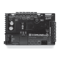
5.5 CONDOR 500 / CONDOR 500 S - connection diagram of the motors
DELAY OF THE MOTOR no.2
1 2
1
2
CONDOR 500 CONDOR 500 S
2
MOTORS
DELAY
MOT. 2
1
ON
2
SW1
DIP1 ON = 2 motors congu-
ration
DIP2 OFF = Delay of motor no. 2
INV
OFF
INV
MOT. 2
1
ON
2
SW2
DIP1 OFF = inversion MOTOR
no. 1 disabled
DIP2 ON = inversion MOTOR no.
2 enabled
DELAY OF THE MOTOR no.1