37
COMUNELLO ®Copyright 2019 - All rights reserved
ENGLISH
EXTENDED
MENU 2
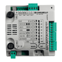
• Press the SELECT button and scroll the LED menu until
you reach the LEV LED;
• Press SET twice to access the EXTENDED menu 2.
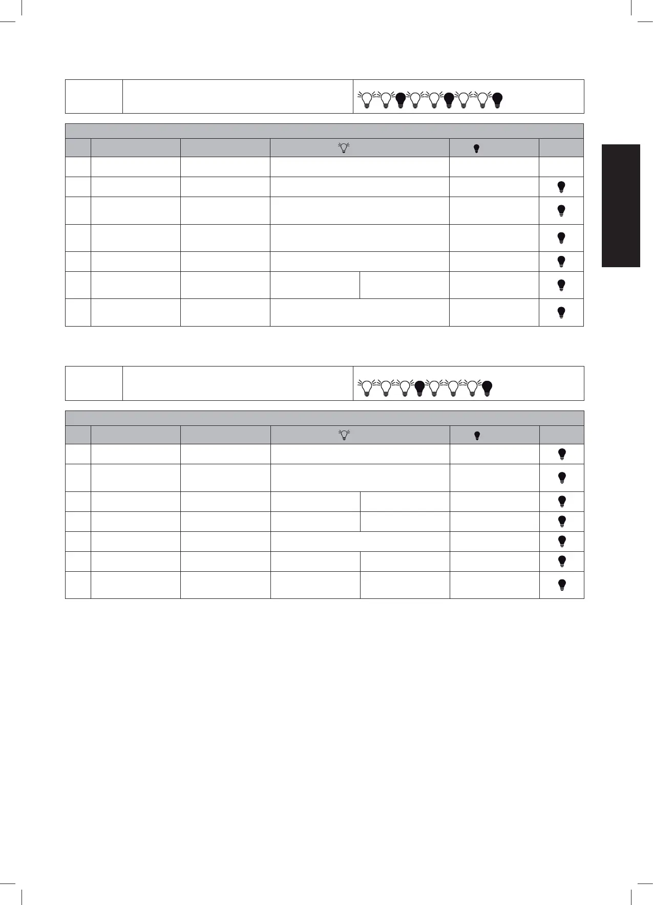
il LED della funzione LEV LAMPEGGIA con questa frequenza:
LIVEL 2 - EXTENDED MENU 2
LED FUNCTION DESCRIPTION LED ON LED OFF DEFAULT
L1 BRAKE Enabling of the electronic
brake
Always enabled Always enabled
L2 STEP BY STEP 1 Step-By-Step logic Open-Stop-Close-Stop (It DOESN'T close after the pause
time in a partial opening phase)
Disabled function
L3 ALWAYS CLOSE Enables the sending of a
CLOSE command when the
power is turned on again
Enabled function Disabled function
L4 FOLLOW ME The motor automatically
closes in 5 sec after passing
through DS1 photocell
Enabled function Disabled function
L5 PEDESTRIAN TIME Storage of motor no.1 partial
stroke with slowdowns
Partial stroke of motor no.1 stored 10 sec., without slowdowns
L6 2°CH MONOSTABLE /
BISTABLE/TIMED MONO.
Setting the aux. relay of the
2°CH as Bistable / Monosta-
ble /Temporised monostable
Bistable command Temporized 3 min. Monostable command
(impulsive)
L7 REMOTELY PROGRAMMING Enable the remote control
memory function without
acting on the control unit
Enabled function Disabled function
Table 4
The fourth and last menu is dened as EXTENDED 3 and to access the programmable functions follow the instructions given in Table 5:
EXTENDED
MENU 3
• Press the SELECT button and scroll the LED menu until
you reach the LEV LED;
• Press SET 3 times to access the EXTENDED menu 3.
The LED of the LEV function FLASHES with this frequency
LIVEL 3 - EXTENDED MENU 3
LED FUNCTION DESCRIPTION LED ON LED OFF DEFAULT
L1 SOFT STOP Setting of gradual slowdown
at the end of the movement
Enabled function Disabled function
L2 SOFT START Setting of gradual slowdown
at the beginning of the
movement
Enabled function Disabled function
L3 RELEASE STROKE MAX
FORCE/ RELEASE STROKE
Activation of the push in ope-
ning for electric lock release
Enabled function at the max
FORCE
Enabled function - FORCE
trimmer
Disabled function
L4 SLAM LOCK MAX FORCE /
SLAM LOCK
Activation of the push in clo-
sing for electric lock release
Enabled function at the max
FORCE
Enabled function - FORCE
trimmer
Disabled function
L5 ELS / CMD PED Activation of the electric lock
as PPED input
Enabled function Disabled function
L6 LAMP / L.CORT L.SPIA /
LAMP L.CORTESIA
Flashing light set as pilot light
or courtesy light
Flash. → Courtesy light
Flash.
→
court. light.; Pilot
light
→
Flash.
Flashing light
L7 PRELAMP / LAMP IN PAUSA Activation of the pre-ash for
3 s. before the CLOSE cycle /
Flashing in pause time
Preash in CLOSE Fllash in pause time Disabled function
Table 5
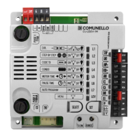
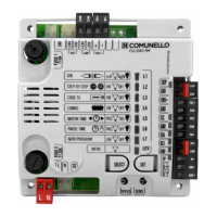
ATTENTION: The control unit allows to be programmed if all the safety devices (N.C. inputs on terminals) grant a contact closed.
FOTO + Photocell control and power supply
LAMP 24V Signal light output 24Vac
GND Common GND input
DS2 Safety device input 2 (NC)
DS1 Safety device input 1 (NC)
STOP 8K2 Block / 8K2 input
GND Common GND input
P PED: Ingresso Puls. Pedestrian/Single Door/open button input
(NO)
PP: Open-close/close command button input (NO)
ELS + Electric lock output +24Vdc
ELS - Electric lock output -
24V 5W Services output (+24Vdc)
GND: Common GND input
SPIA+24V LED: Output indicator lamp (+24 V / 4 W)
ANT-: Chassis ground input (sheath)
ANT+: Antenna hot pin input
CN3:
ENC1 +: Motor 1 Encoder power supply input
7 DETAILED DESCRIPTION OF ALL
FUNCTIONS
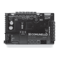
7.1 ELECTRICAL CONNECTIONS
L: 230 V~ Line input (Phase)
N: 230 V~ Line input(Neutral)
LAMP 230~: Flashing Light Output 1 (230 V~ Neutral)
LAMP 230~: Flashing Light Output 1 (230 V~ Phase)
MOT1 OPEN: Operator 1 opening output
MOT1 COM: Operator 1 output common
MOT1 CLOSE: Operator 1 closing output.
MOT2 OPEN2: Operator 2 opening output
MOT2 COM2: Operator 2 output common
MOT2 CLOSE2: Operator 2 closing output
CN2:
2nd CH: Aux Radio CH Output (Free Contact max load 30V DC 1A)
2nd CH: Aux Radio CH Output (Free Contact max load 30V DC 1A)