39
COMUNELLO ®Copyright 2019 - All rights reserved
ENGLISH
procedure.
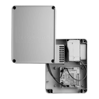
7.3.1 MOTOR 1 OR MOTOR 2 DELAY CONTROL AND ENABLING OF 1
OR 2 MOTORS
1
1
ON
2
MOTOR
NOT
CONSID.
2
MOTORS
MOTOR
2 DELAY
2
MOTORS
MOTOR
1 DELAY
1
ON
2 1
ON
2
SW1 SW1 SW1
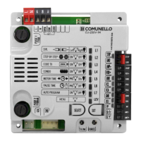
The electronic control unit is equipped with a dip-switch SW1 that is used to
select operation with 1 or 2 motors and to dene which of the two starts rst
and which starts second.
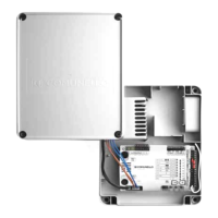
7.3.2 MOTOR 1 AND MOTOR 2 STROKE DIRECTION
INV
OFF
INV
OFF
INV
MOT 1
INV
OFF
INV
OFF
INV
MOT 2
INV
MOT 1
INV
MOT 2
1
ON
21
ON
2 1
ON
2 1
ON
2
SW2 SW2 SW2 SW2
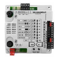
The electronic control unit is equipped with dip-switches that can be used
to change the stroke direction of each connected motor without rewiring
the electrical connections: dip-switch 1 controls Motor 1 while dip-switch 2
controls Motor 2.
7.3.3 DECELERATION (SLOWING):
The motor deceleration function is used in the gates to prevent the mobile
doors from striking at high speed at the end of opening and closure.
When programming the Motor Time, the control unit also allows deceleration
to be programmed in the desired points (before total opening and closure).
Moreover, through the “SLOWING” trimmer it is possible to choose from three
deceleration speed values.
7.3.4. REGULATION OF MOTOR POWER (FORCE):
The electronic control unit is equipped with a “SPEED” trimmer for
adjustment of the speed delivered by the Motors, completely managed by
the microprocessor.
Adjustment can be performed in a range between 50% and 100% of
maximum speed.
Initial starting torque can be set for each movement by feeding the operator
at full power for 2 seconds, even if operator speed control is enabled.
Important notes:
- Initial starting torque is disabled automatically if the Soft Start function is
enabled (see section 8.4.2.);
- A variation of the trimmer “SLOWING” requires the repetition of the learning
procedure, since the times of manoeuvre and slowing may vary.
7.3.5. OBSTACLE DETECTION (ONLY IN VERSION WITH ENCODER):
The electronic control unit is equipped with a “SENS” trimmer, completely
managed by the microprocessor, for adjustment of the opposing Force required
to detect the presence of an obstacle. The adjustment can be made with a trip
time from a minimum of 0.1 seconds to a maximum of 7 seconds
Important notes:
- In the presence of limit switches connected to the control unit, the detection
of the obstacle always causes the reversal of the closing movement and the
inversion for 2 seconds in opening.
- The detection of an obstacle causes the brief inversion of movement in
closure and opening.
- In the absence of limit switches connected to the control unit, detection of
an obstacle will always cause a brief inversion of direction except in the last 5
seconds of the manoeuvre, in which case a stop will be made.
7.3.6 BLACK-OUT
In the case of a black-out and subsequent restoration of the power supply,
the rst manoeuvre will be in opening with a xed speed as set by the trimmer
“SLOWING”; when a mechanical block is encountered, in the absence of an
electrical limit switch, the doors will not be obstructed, but will execute a STOP
(version with encoder). With a subsequent command, the doors will close again
at reduced speed until completely closed. The next manoeuvre will be at the
speeds set by the trimmers.
8 DETAILED DESCRIPTION OF THE
PROGRAMMING
PROGRAMMING:
SELECT key: it determines the type of function to be memorized, as indicated
by the blinking of the LED.
By pressing the key several times, it is possible to scroll the menu and move to
the desired function. The selection remains active for 10 seconds, displayed by
the ashing LED; when this interval elapses, the control unit exits programming.
SET key: it conrms and changes the programming according to the type of
function determined by the SELECT key.
Following conrmation, the respective LED remains on / off for about 2 sec. and
then starts ashing again.
Important notes: the function of the SET key can also be replaced by the remote
control if previously programmed (LED L2 CODE TX lit).
Programming enabled only with the closure of N.C contacts enabled.
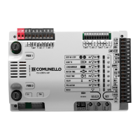
8.1 MAIN MENU
L1 STEP BY STEP Step-by-step Automatic (Open-Close)
L2 CODE TX Remote control stored No remote control stored
L3 CONDO ON OFF
L4 MOTOR TIME Complete stroke stored 30 s. (no slowdowns)
L5 PAUSE TIME With automatic closure OFF
L6 DELAY ON OFF
L7 PRG AUTOM ON OFF
LEV MENÙ ON
8.1.1 LED L1 - STEP BY STEP or OPEN-CLOSE:
Programming
In the default conguration the control unit is set with “Step-By-Step”
operating logic enabled (LED no.1 ON);
if the “Automatic Open-Close” operating logic is required (LED no.2 OFF),
proceed as follows:
• By the key SELECT, position yourself on the blinking LED no.1;
• Press the SET key;
• The LED L1 turns off and programming will be completed.
Repeat the procedure if you wish to restore the previous conguration.
8.1.1. LED L2 - CODE TX:
CODE TX: Remote controls storage
Up to 120 remotes with different codes of either the xed or the rolling code
type can be saved on the control unit
Remote control code programming of the total opening (Mot. no. 1 + Mot.
no.2):
• By the key SELECT, position yourself on the blinking LED 2 “CODE TX”;
• Press key SET once to memorize the PP channel;
• Send the selected code with the remote control;
• The LED L2 will remain steady on for a second to indicate that
programming has been completed;
• The LED L2 starts to blink again to indicate that you have 10 additional
sec. to store a new code;
• On expiry of those 10 sec.the LED L2 will remain steady on.
Remote control code programming of the partial / pedestrian opening
(Mot. no. 1):
• By the key SELECT, position yourself on the blinking LED L2 “CODE TX”;
• Press key SET twice to memorize the PPED channel and the led will
modify its blinking (110110110);
 Loading...