25
COMUNELLO ®Copyright 2019 - All rights reserved
ENGLISH
PRELIMINARY CHECKS
• Check that the product in the pack is intact and in good condition.
• Check that the place of installation is suitable and in compliance with the
minimum dimensions shown in FIG. 1.
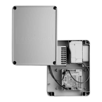
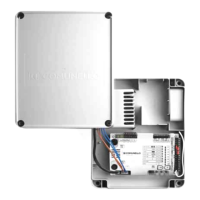
INSTALLATION
• Drill the box in the four corners and then x the control unit to the wall
(FIG. 2).
• Drill a hole in the underside of the box for the cable inlet. (FIG. 3).
The use of cable glands is recommended.
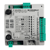
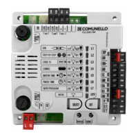
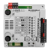
ELECTRICAL CONNECTIONS
CN1 Back-up 24V battery kit connector (AC51)
CN2 Mains power connector 230V~50/60 Hz
CN3 Transformer primary winding (mains voltage)
CN4 Transformer secondary winding (operator power)
CN5 Transformer secondary winding (BUS line power)
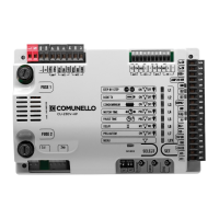
CN6 Metric layout reference
MOT1 +: Operator 1 Output (+)
MOT1-: Operator 1 Output (-)
MOT2 +: Operator 2 Output (+)
MOT2 -: Operator 2 Output (-)
OUT AUX +24V: +24V
Utility Output (AUX Flashing light or Electric Lock)
OUT AUX -24V: -24V
Utility Output (AUX Flashing light or Electric Lock)
FC MOT1 FCC: Operator 1 Closing Limit Switch Input (NC)
FC MOT1 GND: Operator 1 Limit Switch Common Input
FC MOT1 FCA: Operator 1 Opening Limit Switch Input (NC)
ENC MOT1 E1: Operator 1 Encoder Input (2-wire encoder)
ENC MOT1 E2: Operator 1 Encoder Input
ENC MOT2 E1: Operator 2 Encoder input (2-wire encoder)
ENC MOT2 E2: Operator 2 Encoder Input
CN7
ENC MOT1 +: Operator 1 Encoder Power Input
ENC MOT1 GND: Operator 1 Encoder Common Input
ENC MOT1 E: Operator 1 Encoder Signal Input
CN8
8K2-ANT 8K2: Input Stop 8k2
8K2-ANT GND: Common input (8k2 and Antenna)
8K2-ANT ANT+: Antenna Input
CN9
BUS: BUS line input for accessories
FUSES
F1: T3.15A 250V
F2: T15A 250V
F3: T3.15A 250V
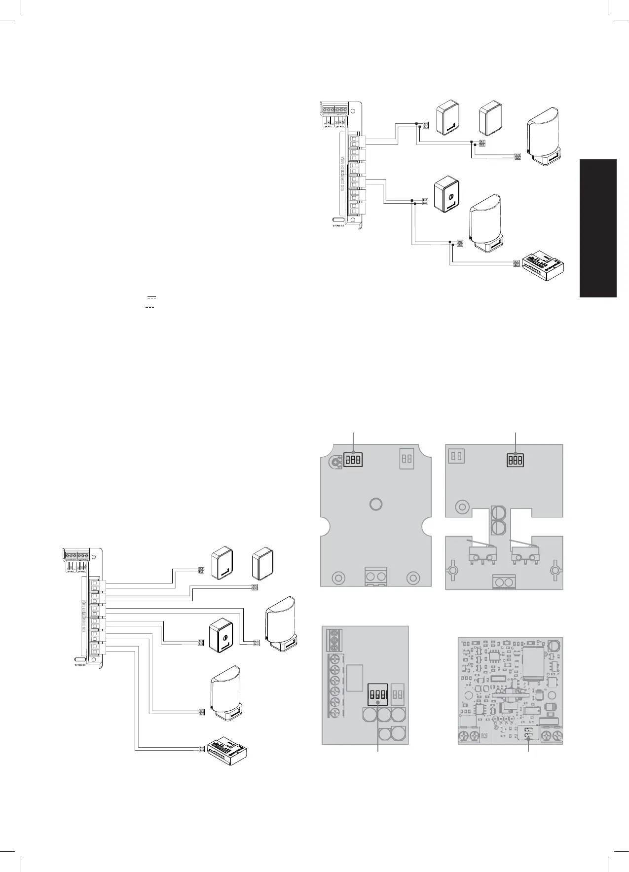
BUS CABLE TO NEUTRAL POINT CONNECTION
BUS CASCADING
ACCESSORY ADDRESS ASSIGNMENT (BUS LINE)
The ONE control unit requires the use of ONE accessories connected
exclusively through digital (BUS) line with 2 non-polarised wires. All
accessories (ashing light, photocells RX and TX, key switch, I/O board,
etc.) must be connected with only two wires (BUS line terminals) to the
control unit. Both the power supply and digital commands to control the
accessories transit on the BUS line.
Every accessory from the same family connected to the BUS line must be
identied by a UNIQUE numeric ID (different from all other accessories of
the same type). Setting the ID of each accessory is done through the DIP-
SWITCHES accessible on the board:
Dip switch ID Dip switch ID
Dip switch ID
DART INDEX
INTERFACE I/O
SWIFT
Dip switch ID