CONCEPT2.COM
Page 3 0914
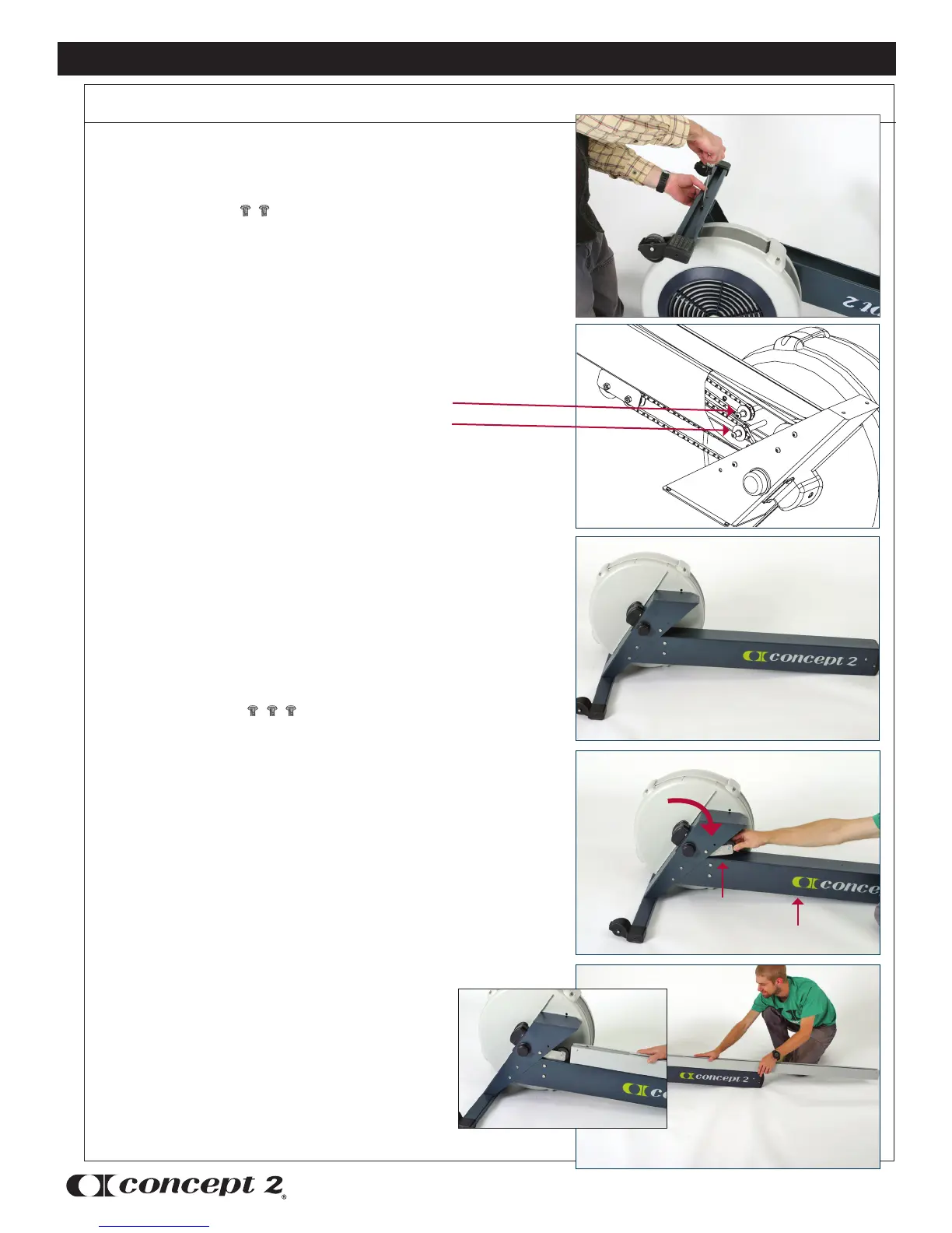
photo A
Step 2: Attach Rear Foot to Flywheel Box
photo C
Assembly Instructions
photo E
CONCEPT2 DYNAMIC INDOOR ROWER
Assembly
(2) 3/8” (.95 cm)
PN 2239
Be sure that caster wheels point back, as shown
in the photo of the assembled Dynamic Indoor
Rower on page 9. Install the two screws and
tighten snugly. See photo A.
Before turning the flywheel box assembly right
side up to continue with assembly, inspect the
chain routing over the chain idler pulleys. See
image B. The chain should be routed around the
chain idler pulleys.
Turn the flywheel box assembly right side up.
See photo C.
Step 3: Install Shuttle Channel
(3) 3/8” (.95 cm)
PN 2239
Important: Pull shuttle down so that
the shuttle lies flat on the return
mechanism box.
See photo D.
Remove the cardboard packaging from inside the
shuttle channel by sliding it out as indicated by the
arrow on the cardboard.
Note: The plastic “floor” remains in the shuttle
channel and is adhered at one end only.
Position the shuttle channel with the slot facing
up, and the flange to the flywheel side. The end
with four holes in it should be away from the
flywheel.
Slide the shuttle channel into the rear leg with
the shuttle positioned inside the shuttle channel.
See image E.
photo D
image B
Shuttle
Shuttle