Do you have a question about the ConMed Sabre 2400 and is the answer not in the manual?
Safety guidelines for electrosurgery use and preparation.
Steps to ensure safe setup and accessory checks before use.
Safety measures for patient setup and environment.
Guidelines for safe operation during procedures.
Safety procedures for maintenance and testing.
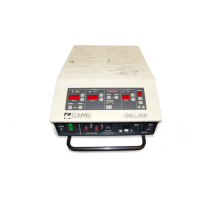
Technical details and performance parameters of the unit.
Definitions of graphical symbols used in the manual.
Procedure for unpacking and checking the unit for damage.
Instructions for mounting and connecting the unit.
Initial steps before operating the unit.
Steps to verify basic operation of controls and indicators.
Testing procedures to confirm operational capabilities.
Identification and function of unit interface elements.
Details of buttons, indicators, and digital displays on the front.
Description of connection jacks and circuit breaker.
Overview of rear panel connectors and power input.
Guidance for using the electrosurgical unit.
Steps for preparing the unit for operation.
How to activate and use the unit during procedures.
Explanation of the unit's internal circuitry and functions.
Description of the unit's functional blocks and interconnections.
Details on the unit's internal power supply circuits.
Description of the main controller components and their features.
Overview of the software controlling unit functions.
Explanation of the display system components.
Description of the RF power amplifier circuit.
Explanation of how RF power is delivered to outputs.
Description of the patient return electrode monitoring system.
Explanation of isolated accessory control circuits.
Overview of maintenance recommendations and features.
Procedures for accessing internal components for service.
Steps to access and replace the power board.
Steps to access and replace the micro-controller board.
Steps to access and replace the display board.
Instructions for cleaning the unit's interior and exterior.
Recommended visual checks for safety and integrity.
Procedures for testing unit performance at regular intervals.
Test for proper electrical grounding of the unit chassis.
Testing of unit indicators, sounds, and control inputs.
Procedure to measure and verify RF output power levels.
Test for RF current leakage to ground.
Testing RF leakage from unused output terminals.
Test for leakage currents at mains frequency.
Procedure to verify the A.R.M. circuitry calibration.
Procedures for calibrating unit parameters.
General information on entering and using CAL Mode.
Information on requirements for power calibration.
Step-by-step guide for calibrating output power.
Procedure to calibrate the Aspen Return Monitor.
Guide to diagnosing and resolving unit problems.
Explanation of error codes displayed by the unit.
Using diagnostic modes for troubleshooting.
Steps to diagnose issues with the watchdog timer.
Troubleshooting steps for the base voltage generator.
Guide to diagnosing waveform generator issues.
Troubleshooting the A.R.M. circuitry.
Steps for troubleshooting the RF amplifier.
Procedure for replacing power amplifier transistors.
Using diagnostic mode to monitor software variables.
Information on how to order replacement parts.
| Category | Electrosurgical Generator |
|---|---|
| Output Power | 240 Watts |
| Line Voltage | 100-240 VAC |
| Frequency | 50/60 Hz |
| Modes | Cut, Blend, Coagulation, Bipolar |
| Weight | 22 lbs |